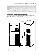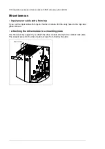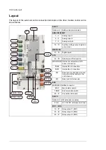
DC connection
The UDC+ and UDC– terminals are intended for common DC configurations of a number
of drives, allowing regenerative energy from one drive to be utilized by the other drives in
the motoring mode. For more information, contact your local ABB representative.
Connecting the control cables
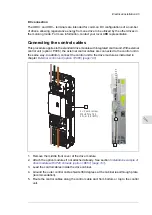
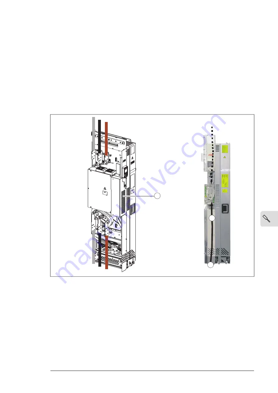
This procedure applies to the standard drive module with integrated control unit. With external
control unit (P906), the external control cables are connected to the control unit in
the same way. In addition, connect the control unit to the drive module as instructed in
chapter
External control unit (P906) (page 195)
.
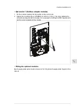
2 × Combi screw
M4×8 Torx T20
2 N·m
1
5
3
(1.5 lbf·ft)
1.
Remove the middle front cover of the drive module.
2.
Attach the option modules if not attached already. See section
drive module with IP20 shrouds (B051) (page 101)
3.
Lead the control cables inside the drive cabinet.
4.
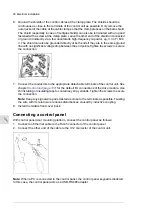
Ground the outer control cable shields 360 degrees at the cabinet lead-through plate
(recommendation).
5.
Route the control cables along the control cable duct from bottom or top to the control
unit.
Electrical installation 95
11
Содержание ACH580-04
Страница 1: ... ABB DRIVES FOR HVAC ACH580 04 drive modules Hardware manual ...
Страница 2: ......
Страница 4: ......
Страница 54: ...54 ...
Страница 88: ...88 ...
Страница 100: ...100 ...
Страница 118: ...118 ...
Страница 122: ...122 ...
Страница 124: ...124 ...
Страница 128: ...3 6 5 5 128 Maintenance ...
Страница 134: ...134 ...
Страница 156: ...R10 standard configuration 156 Dimension drawings ...
Страница 157: ...R10 with E208 0H354 H356 H370 0H371 Dimension drawings 157 ...
Страница 158: ...R10 with option B051 158 Dimension drawings ...
Страница 159: ...R10 with option E208 H356 P906 192 Tools R10 3 1 Dimension drawings 159 ...
Страница 160: ...R10 with option E208 0H371 H356 0H354 H370 P906 Tools 191 R10 2 1 160 Dimension drawings ...
Страница 161: ...R10 with option B051 P906 190 Tools R10 1 1 Dimension drawings 161 ...
Страница 162: ...R11 standard configuration 162 Dimension drawings ...
Страница 163: ...R11 with option E208 0H371 H356 0H354 H370 Dimension drawings 163 ...
Страница 164: ...R11 with option B051 164 Dimension drawings ...
Страница 165: ...R11 with option E208 H356 P906 Dimension drawings 165 ...
Страница 166: ...R11 with option E208 0H371 H356 0H354 H370 P906 166 Dimension drawings ...
Страница 167: ...R11 with option B051 P906 Dimension drawings 167 ...
Страница 186: ... Declaration of conformity 186 The Safe torque off function ...
Страница 206: ...Dimension drawing 206 External control unit option P906 ...
Страница 211: ...Dimension drawing The dimensions are in millimeters and inches CHDI 01 115 230 V digital input extension module 211 ...
Страница 212: ...212 ...
Страница 224: ...224 ...
Страница 226: ...226 ...
Страница 234: ...234 ...


