background image

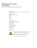
ACH580-01 VxR, UL Type 1

Frame R1/R2

Base drive replacement instructions

Purpose or Scope
The following are the instructions for replacing an ACH580-01 UL Type 1 and 12 (Frames 
R1 & R2) drive in VxR enclosures.

Equipment required*:


– Replacement drive (see note below)


– T20 bit


– T30 bit


– PZ2 bit


– PZ3 bit


– Torque wrench


– Zip ties

Basic overview of steps


– Back-up drive parameters (if you can)


– Remove power and verify after 5 minutes


– Remove covers


– Disconnect all wiring


– Remove drive


– Prepare replacement drive


– Remove conduit assembly


– Install in reverse order


– Check connections


– Power drive


– Reprogram and test

Notes and cautions

CAUTION! Review complete safety and electrical considerations prior 
to replacing the drive. See ACH580 IOM (3AXD50000049127).

CAUTION! Two people are recommended for this job. The drive is 
heavy and can fall, causing property damage and injury.

* Not all of these tools are needed for each frame size.

Содержание ACH580-01 VxR R1

Страница 1: ...rive parameters if you can Remove power and verify after 5 minutes Remove covers Disconnect all wiring Remove drive Prepare replacement drive Remove conduit assembly Install in reverse order Check connections Power drive Reprogram and test Notes and cautions CAUTION Review complete safety and electrical considerations prior to replacing the drive See ACH580 IOM 3AXD50000049127 CAUTION Two people a...

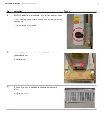
Страница 2: ...r to disconnecting power Turn off source power and wait 5 minutes for the DC bus capacitors to discharge Turn handle to the off position 2 Using a T20 bit loosen and remove two 2 M4x16 screws securing the enclosure cover Save hardware 3 Remove drive cover by pushing up on the sides as indicated by arrow Recycle drive cover ...

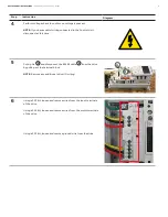
Страница 3: ...l Unit disconnect at this time 5 Cut zip tie A and disconnect the RS485 cable B from the drive by pulling out the terminal block NOTE Remove any additional drive I O wiring 6 Using a PZ2 bit loosen and remove wires from the input terminals of the drive Using a PZ2 bit loosen and remove wires from the motor terminals of the drive Using a PZ3 bit loosen and remove ground wire from the drive A B ...

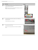
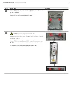
Страница 4: ...ive four 4 turns of the screw NOTE Do not remove the screw completely Only loosen enough to be able to lift the drive off the screws 8 Using a T30 bit loosen and remove the top two 2 M6 screws securing the drive Carefully lift the drive out of channel 9 Unpack the replacement drive Remove drive cover by pushing up on the sides as indicated by arrow ...

Страница 5: ...x8 screws Remove conduit assembly Recycle the conduit assembly and hardware 11 CAUTION Use two people to install the drive Slide the drive mounting holes over the bottom two 2 screws and slide drive in place Using a T30 bit replace the two 2 M6 screws that were removed earlier Torque all four 4 mounting screws to 27 in lb 3 Nm ...

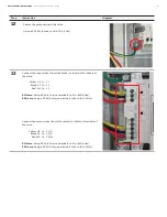
Страница 6: ...inals of the drive Yellow U1 to L1 Black V1 to L2 Red W1 to L3 R1 Frame Using PZ2 bit torque terminals to 5 in lb 0 5 Nm R2 Frame Using a PZ2 bit torque terminals to 14 in lb 1 5 Nm Connect the motor wires from 1M contactor to Motor Terminals of the drive Yellow U2 to T1 U Black V2 to T2 V Red W2 to T3 W R1 Frame Using PZ2 bit torque terminals to 5 in lb 0 5 Nm R2 Frame Using a PZ2 bit torque term...

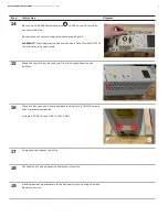
Страница 7: ...s not support Safe Torque Off STO functionality in bypass mode 15 Place the top of the drive cover on first then press down on the bottom 16 Place enclosure cover in place and secure using two 2 M4x16 screws that were removed earlier Using a T20 bit torque to 14 in lb 1 5 Nm 17 Power and reprogram the drive 18 Test and verify drive operation and motor direction 19 Back up and save parameters to th...

Отзывы: