


1-158
ACH550-UH User’s Manual
Parameters
4025
WAKE-UP DEV
Depends on Units
-
0.0%
and Scale
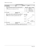
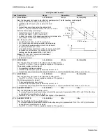
Defines the wake-up deviation – a deviation from the setpoint greater than this value, for at least the time period
4026
WAKE
-
UP
DELAY
, re-starts the PID controller.
• Parameters 4006 and 4007 define the units and scale.
• Parameter 4005 = 0,
Wake-up level = Setpoint - Wake-up deviation.
• Parameter 4005 = 1,
Wake-up level = Se Wake-up deviation.
• Wake-up level can be above or below setpoint.
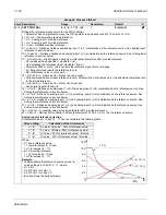
See the figures with parameter 4023:
• C = Wake-up level when parameter 4005 = 1
• D = Wake-up level when parameter 4005 = 0
• E = Feedback is above wake-up level and lasts longer than 4026
WAKE
-
UP
DELAY
– PID function wakes up.
• F = Feedback is below wake-up level and lasts longer than 4026
WAKE
-
UP
DELAY
– PID function wakes up.
4026
WAKE-UP DELAY
0.00…60.00 s
0.01 s
0.50 s
Defines the wake-up delay – a deviation from the setpoint greater than 4025
WAKE
-
UP
DEV
, for at least this time
period, re-starts the PID controller.
4027
PID 1 PARAM SET
-6…14
1
0 (
SET
1)
Process PID (PID1) has two separate sets of parameters, PID set 1 and PID set 2.
• PID set 1 uses parameters 4001…4026.
• PID set 2 uses parameters 4101…4126.
PID
1
PARAM
SET
defines which set is selected.
0 =
SET
1 – PID Set 1 (parameters 4001…4026) is active.
1 =
DI
1 – Defines digital input
DI
1 as the control for PID Set selection.
• Activating the digital input selects PID Set 2.
• De-activating the digital input selects PID Set 1.
2…6 =
DI
2…
DI
6 – Defines digital input
DI
2…
DI
6 as the control for PID Set selection.
• See
DI
1 above.
7 =
SET
2 – PID Set 2 (parameters 4101…4126) is active.
8…11 =
TIMED
FUNC
1…4 – Defines the Timed function as the control for the PID Set selection (Timed function de-
activated = PID Set 1; Timed function activated = PID Set 2)
• See
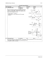
12 = 2-
ZONE
MIN
– The drive calculates the difference between setpoint 1 and feedback 1 as well as setpoint 2 and
feedback 2. The drive will control the zone (and select the set) that has a larger difference.
• A positive difference (a setpoint higher than the feedback) is always larger than a negative difference. This keeps
feedback values at or above the setpoint.
• Controller does not react to the situation of feedback above setpoint if another zone’s feedback is closer to its
setpoint.
13 = 2-
ZONE
MAX
– The drive calculates the difference between setpoint 1 and feedback 1 as well as setpoint 2 and
feedback 2. The drive will control the zone (and select the set) that has a smaller difference.
• A negative difference (a setpoint lower than the feedback) is always smaller than a positive difference. This
keeps feedback values at or below the setpoint.
• Controller does not react to the situation of feedback below setpoint if another zone’s feedback is closer to its
setpoint.
14 = 2-
ZONE
AVE
– The drive calculates the difference between setpoint 1 and feedback 1 as well as setpoint 2 and
feedback 2. In addition, it calculates the average of the deviations and uses it to control zone 1. Therefore one
feedback is kept above its setpoint and another is kept as much below its setpoint.
-1 =
DI
1(
INV
) – Defines an inverted digital input
DI
1 as the control for PID Set selection.
• Activating the digital input selects PID Set 1.
• De-activating the digital input selects PID Set 2.
-2…-6 =
DI
2(
INV
)…
DI
6(
INV
) – Defines an inverted digital input
DI
2…
DI
6 as the control for PID Set selection.
• See
DI
1(
INV
) above.
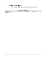
Group 40: Process PID Set 1
Code Description Range
Resolution
Default
S
Содержание ACH550-BCR
Страница 4: ...iv Manual contents ...
Страница 5: ...ACH550 UH User s Manual 1 1 ACH550 UH HVAC Drives 1 550 HP User s Manual 2016 ABB All Rights Reserved ...
Страница 6: ......
Страница 12: ...1 8 ACH550 UH User s Manual Table of contents ...
Страница 36: ...1 32 ACH550 UH User s Manual Installation ...
Страница 70: ...1 66 ACH550 UH User s Manual Application macros ...
Страница 335: ...ACH550 UH User s Manual 1 331 Technical data ...
Страница 348: ......
Страница 382: ...2 36 ACH550 E Clipse Bypass User s Manual Start up ...
Страница 398: ...2 52 ACH550 E Clipse Bypass User s Manual Bypass functions overview ...
Страница 406: ...2 60 ACH550 E Clipse Bypass User s Manual Application macros ...
Страница 544: ...2 198 ACH550 E Clipse Bypass User s Manual Embedded fieldbus ...
Страница 584: ...2 238 ACH550 E Clipse Bypass User s Manual Diagnostics ...
Страница 608: ......
Страница 612: ...3 6 ACH550 UH User s Manual Table of contents ...
Страница 622: ...3 16 ACH550 PCR PDR User s Manual Installation ...
Страница 641: ......


