8
)
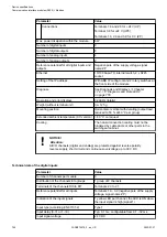
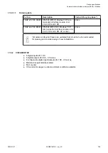
In case of an I/O module doesn’t support hot swapping, do not perform any
hot swap operations (also not on any other terminal units (slots)) as modules
may be damaged or I/O bus communication may be disturbed.
9
)
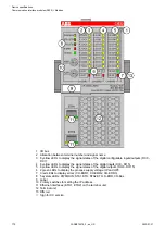
Diagnosis for hot swap available as of version index F0.
State LEDs
The LEDs are located at the front of module. There are 2 different groups:
● The 5 system LEDs (PWR, STA1 ETH, STA2 ETH, S-ERR and I/O-Bus) show the operation
state of the module and display possible errors.
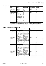
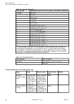
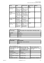
● The 27 process LEDs (UP, UP3, inputs, outputs, CH-ERR1 to CH-ERR3) show the process
supply voltage and the states of the inputs and outputs and display possible errors.
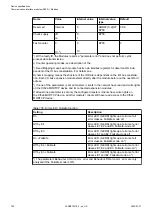
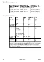
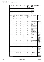
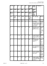
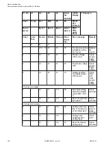
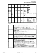
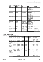
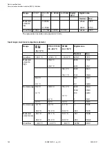
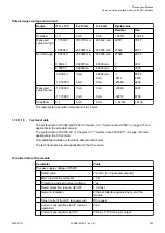
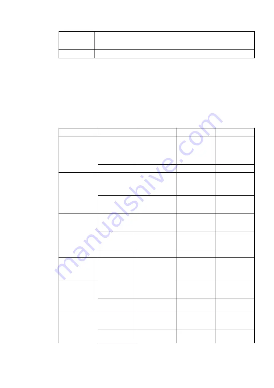
Table 161: States of the 5 system LEDs
LED
Color
OFF
ON
Flashing
PWR/RUN
Green
Process supply
voltage missing
Internal supply
voltage OK,
module ready for
communication
with IO Controller
Start-up / pre-
paring communi-
cation
Yellow
---
---
---
STA1 ETH
(System LED
"BF")
Green
---
Device config-
ured, cyclic data
exchange run-
ning
Device config-
ured, acyclic data
exchange run-
ning
Red
---
Communication
error (timeout)
appeared
IP address error
STA2 ETH
(System LED
"SF")
Green
Device has valid
parameters
Device is running
parameterization
sequenze
Device has no
parameters
Red
---
---
Device has
invalid parame-
ters
S-ERR
Red
No error
Internal error
--
I/O-Bus
Green
No expansion
modules con-
nected or com-
munication error
Expansion
modules con-
nected and
operational
---
ETH1
Green
No connection at
Ethernet inter-
face
Connected to
Ethernet inter-
face
---
Yellow
---
Device is trans-
mitting telegrams
Device is trans-
mitting telegrams
ETH2
Green
No connection at
Ethernet inter-
face
Connected to
Ethernet inter-
face
---
Yellow
---
Device is trans-
mitting telegrams
Device is trans-
mitting telegrams
Device specifications
Communication interface modules (S500) > Modbus
2022/01/31
3ADR010278, 3, en_US
760

