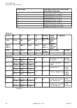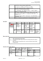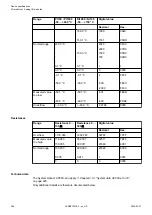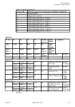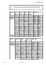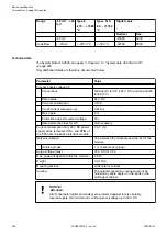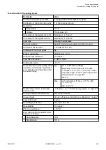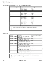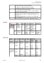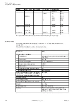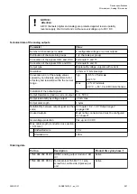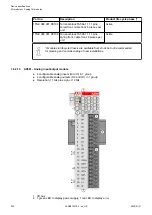
Table 77: Channel configuration
2
)
Internal value
Operating modes for the analog inputs, individually configurable
0
Not used (default)
21
Voltage -80 mV...+80 mV
24
Thermocouple J-type -210 °C...+1200 °C
25
Thermocouple K-type -270 °C...+1372 °C
26
Thermocouple R-type -50 °C...+1768 °C
27
Thermocouple S-type -50 °C...+1768 °C
28
Thermocouple T-type -270 °C...+400 °C
29
Thermocouple E-type -270 °C...+1000 °C
30
Thermocouple N-type -270 °C...+1300 °C
Diagnosis
E1...E4
d1
d2
d3
d4
Identifier
000...063
AC500
display
<− Display in
Class
Comp
Dev
Mod
Ch
Err
PS501
PLC
browser
Byte 6
Bit 6...7
-
Byte 3
Byte 4
Byte 5
Byte 6
Bit 0...5
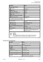
PNIO
diagnosis
block
Class
Interface
Device
Module
Channel
Error
Identifier
Error message
Remedy
1
)
2
)
3
)
4
)
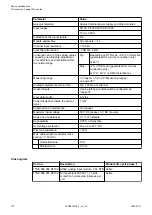
Module error
3
14
1...10
31
31
19
Checksum error in the
I/O module
Replace
I/O module
11 / 12
ADR
1...10
3
14
1...10
31
31
9
Overflow diagnosis
buffer
Restart
11 / 12
ADR
1...10
3
14
1...10
31
31
26
Parameter error
Check
master
11 / 12
ADR
1...10
3
14
1...10
31
31
11
Process voltage too low Check
process
voltage
11 / 12
ADR
1...10
Channel error
4
14
1...10
1
0...3
48
Analog value overflow
or broken wire at an
analog input
Check
input value
or terminal
11 / 12
ADR
1...10
4
14
1...10
1
0...3
7
Analog value underflow
at an analog input
Check
input value
11 / 12
ADR
1...10
Remarks:
Device specifications
I/O modules > Analog I/O modules
2022/01/31
3ADR010278, 3, en_US
377

