background image

Operating Instructions 


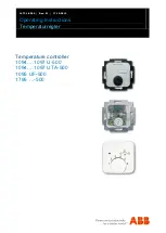
Temperaturregler 


Setup and function


Operating Instructions | 1473-1-8290 

— 6 — 


Pos: 20 /#Neustr uktur#/Online-Dokumentati on (+KN X)/Überschriften (--> Für all e D okumente <--)/1. Ebene/A - F /Aufbau und Funkti on @ 11\mod_1279185435352_15.docx @ 83027 @ 1 @ 1 


Setup and function 


Pos: 21 /#Neustr uktur#/Online-Dokumentati on (+KN X)/Aufbau  und Funkti on/T emperaturregler /Ver wendung 1094....1097, 1098 @  26\mod_1342766379475_15.docx @ 224403 @  @ 1 


The temperature controller is used to control the temperature in closed rooms. 
 

Pos: 22 /#Neustr uktur#/Online-Dokumentati on (+KN X)/Überschriften (--> Für all e D okumente <--)/2. Ebene/A - F /Funkti ons- und Ausstattungsmer kmal e @ 23\mod_1336557630140_15.docx @ 209136 @  2  @  1 


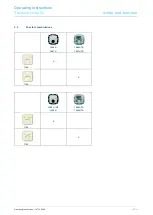
6.1 

Features of function and equipment 


Pos: 23 /#Neustr uktur#/Online-Dokumentati on (+KN X)/Aufbau  und Funkti on/T emperaturregler /Funkti onen  1094....1097 @ 26\mod_1342708498968_15.docx @ 224389 @  @ 1 


Article no. 

Features / Function 

1094 … 

  Opens when the set temperature is reached. 

  With separate connection for time-controlled reduction of nighttime temperature (4K). 

  Servo valves of "closed when de-energized“ design are required for the controller. 

1095 … 

  Opens when the set temperature is reached. 

  With normally open contact (not applicable for 1095 UF) 

  With separate connection for time-controlled reduction of nighttime temperature (4K). 

  With installed sliding switch and control lamp for nighttime temperature reduction (4 K). 

  Servo valves of "closed when de-energized“ design are required for the controller. 

… UF 

  With normally closed contact 

  With remote sensor (external temperature sensor for mounting in the floor) and thermal feedback. 

  For electric underfloor heating 

  Opening of the relay contact, when the set temperature is reached. 

1096 … 

  Opens when the set temperature is reached. 

  With separate connection for time-controlled reduction of nighttime temperature (4K). 

  With installed sliding switch and control lamp for nighttime temperature reduction (4 K). 

  Servo valves of "closed when de-energized“ design are required for the controller. 

1097 … 

  With switchover contact (heating / cooling) 

  Servo valves of "closed when de-energized“ design are required for the controller. 

… UTA 

  With display of actual temperature 

  -  Temperature display in steps of 0.5°C 

  Display accuracy: ±0,5°C for load currents 

of ≤2 A


– Display accuracy: ±1,5°C for load currents of >2 A 

  Automatic controller calibration 


Pos: 24 /#Neustr uktur#/Online-Dokumentati on (+KN X)/Steuer modul e - Online-Dokumentation (--> Für  alle Dokumente <--)/++++++++++++ Seitenu+++++++++++ @ 9\mod_1268898668093_0.docx  @  52149 @   @ 1 


Содержание 1795 500 Series

Страница 1: ...aturregler Pos 2 N eustruktur Online Dokumentation KN X Titelbl ätter Temper aturregler Titelbl att 1094 1097 26 mod_1342698041601_15 docx 224303 1 Temperature controller 1094 1097 U 500 1094 1097 UTA 500 1095 UF 500 1795 500 Ende der Liste für Textmar ke Cover ...

Страница 2: ... Environment 3 4 Operation 4 5 Technical data 5 6 Setup and function 6 6 1 Features of function and equipment 6 6 2 Possible combinations 7 7 Installation and electrical connection 8 7 1 Requirements for the electrician 8 7 2 Mounting 8 7 3 Electrical connection 10 8 Commissioning 11 8 1 Calibrating the display of the actual temperature value applies only to UTA devices 11 8 2 Offset function scal...

Страница 3: ...all e D okumente 1 Ebene U Z U mwelt 18 mod_1302614158967_15 docx 103383 1 1 3 Environment Pos 11 Neustr uktur Online Dokumentati on KN X Sicherheitshinweise und Hinweise Für alle Dokumente Hinweise U mwelt Hi nweis U mwelt Hi nweis El ektr ogeräte 18 mod_1302763973434_15 docx 103500 1 Consider the protection of the environment Used electric and electronic devices must not be disposed of with dome...

Страница 4: ...temperature 1 5 C The temperature is continuously variable with the adjusting knob C The difference in temperature between two digits is approximately 5 C For temperature adjustment and values see the opposite columns 2 10 C 3 15 C 4 20 C 5 25 C 6 30 C Switch position for external temperature reduction Switch position for selected temperature Switch position for continuous temperature reduction Fi...

Страница 5: ...V AC 10 50 Hz 1094 1095 1095 UF 1097 1096 Switching capacity 10 4 A 230 V AC 16 A 230 V AC 1 1 A 24 V AC 5 2 A 230 V AC 1094 1095 1095 U 1096 1097 Connection 1 5 mm 2 5 mm 2 x 2 5 mm 1 x 4 mm 1094 1095 1095 1097 1095 UF Temperature adjustment range 1 6 5 30 C 1 6 10 50 C 1094 1095 1095 1097 1095 UF Temperature reduction 4 K Switching temperature difference 0 5 K Protection type IP 20 EN 60529 Temp...

Страница 6: ...erature is reached With normally open contact not applicable for 1095 UF With separate connection for time controlled reduction of nighttime temperature 4K With installed sliding switch and control lamp for nighttime temperature reduction 4 K Servo valves of closed when de energized design are required for the controller UF With normally closed contact With remote sensor external temperature senso...

Страница 7: ...09520 2 1 6 2 Possible combinations Pos 26 Neustr uktur Online Dokumentati on KN X Kombi nationsmöglichkeiten Temper aturregler Kombinati onsmöglichkeiten 1094 1097 26 mod_1342766499439_15 docx 224417 1 1094 U 1097 U 1094 UTA 1097 UTA 1794 X 1794 X 1095 U UF 1096 U 1095 UTA 1096 UTA 1795 X 1795 X Pos 27 Neustr uktur Online Dokumentati on KN X Steuer modul e Online Dokumentation Für alle Dokumente ...

Страница 8: ...t installation can cause serious damage to property e g due to fire The minimum necessary expert knowledge and requirements for the installation are as follows Apply the five safety rules DIN VDE 0105 EN 50110 1 Disconnect from power 2 Secure against being re connected 3 Ensure there is no voltage 4 Connect to earth and short circuit 5 Cover or barricade adjacent live parts Use suitable personal p...

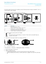
Страница 9: ...s or windows approx 30 cm B Avoid mounting on cold walls thermal bridges C Avoid draught and heat radiation such as direct sunlight D Avoid heat radiation from adjacent devices dimmers 1 Connect the device according to the circuit diagram Note In connection with hot water heating servo valves of closed when de energized design are required for the controller 2 Fix the device in the flush mounted b...

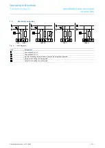
Страница 10: ...Online Dokumentati on KN X Anschluss Temperaturregl er Anschluss 1094 1097 26 mod_1342777244577_15 docx 224461 1 1094 1095 1095 UF 1097 1096 U Fig 5 Circuit diagrams Icon Assignment Connections 24 V AC Connections 24 V AC Input for activating the temperature reduction see nighttime reduction Output for controlling the heating load Output for controlling the cooling load Pos 39 Neustr uktur Online ...

Страница 11: ...onnected for calibrating the display After the connection the heating system is switched on automatically for about 20 minutes During this time the CA symbol will be displayed After this the display adjusts itself to the room temperature within a few minutes Before repeating the calibration procedure the unit must be disconnected from the power supply for at least 8 minutes 8 2 Offset function sca...

Страница 12: ... 2351 956 1700 Notice We reserve the right to at all times make technical changes as well as changes to the contents of this document without prior notice The detailed specifications agreed to at the time of ordering apply to all orders ABB accepts no responsibility for possible errors or incompleteness in this document We reserve all rights to this document and the topics and illustrations contai...

Отзывы: