Publication No. 500-9300527837-000 Rev. A.0
Functional Description 49
5.15 Board Management Microcontroller (optional)
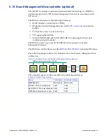
The SBC347A contains an optional microcontroller functioning as a BMM for
implementation of the VPX System Management function in accordance with
VITA 46.11.
The BMM is connected to the following interfaces:
• RS232 interface (connected to COM3)
• Backplane System Management bus (on the
) via isolation
buffers
• I
2
C bus (for access to sensor devices)
• VPX geographic address
• Internal Field Replaceable Unit (FRU) ROM containing the board part
number and serial number
The BMM can reset or power off the SBC347A in response to a System
Management request.
The BMM can control the state of the
to indicate BIT status.
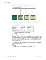
The following diagram shows the onboard sensor and System Management bus
architecture:
Figure 5-5 Onboard Sensor and System Management Bus Architecture
The onboard sensors can be accessed at the following addresses:
Table 5-13 BMM I
2
C Bus Devices
Device
7-bit Address 8-bit Write Address
BMM (Master)
Master only
Master only
ADT461 CPU core temperature
0x4C
0x98
ispPOWR-11014A Power Manager 0x40
0x80
LM92 board temperature sensor
0x48
0x90
CPU
Remote
Temperature
Power
Manager
Board
Temperature
BMM
(Master)
Buffer
BMM bus (devices powered from 3.3V_AUX)
VPX
Connector


