


82 PPC11A 6U VME Single Board Computer
Publication No. PPC11A-HRM/1
5.16.7 GPIO (7-0) Interrupt Both Edges Register (Offset 0x676)
For each GPIO:
1 = Both-edges mode enabled
0 = Both-edges mode disabled (default)
When enabled, Both-edges mode causes interrupts to be generated on both rising
and falling edges.
NOTE
The GPIO bit must be in Edge mode for Both-edges mode to work.
5.16.8 GPIO (7-0) Interrupt Status/Clear Register (Offset 0x677)
For each GPIO:
1 = Interrupt pending
0 = No interrupt (default)
Write a ‘1’ to a bit to clear the interrupt pending status.
5.16.9 GPIO (7-0) Availability Register (Offset 0x678)
For each GPIO:
1 = GPIO available
0 = GPIO not available
This register allows software to easily determine which of the GPIO7-0 signals are
available on the PPC11A. All GPIO signals use shared backplane pins and are only
available when the PPC11A is configured with the appropriate build option.
5.16.10 GPIO (7-0) Interrupt Select Register (Offset 0x679)
For each GPIO:
1 = Interrupt routed to secondary GPIO interrupt output
0 = Interrupt routed to main GPIO interrupt output (default)
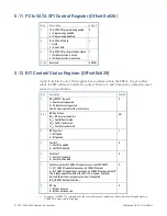
5.16.11
GPIO (7-0) Interrupt Non-Maskable Register (Offset 0x67A)
For each GPIO:
1 = GPIO interrupt is non-maskable
0 = GPIO interrupt is maskable (default)
Once a GPIO interrupt has been set as non-maskable in this register, it cannot be set
to maskable again until after the next reset has occurred.
Содержание PPC11A
Страница 1: ...Hardware Reference Manual PPC11A 6U VME Single Board Computer Edition 1 Publication No PPC11A HRM 1 ...
Страница 27: ...Publication No PPC11A HRM 1 Functional Description 27 Figure 4 2 Block Diagram T2081 ...
Страница 113: ...Publication No PPC11A HRM 1 Connectors 113 Figure 6 2 Rear Connector Position ...


