


Publication No. PPC11A-HRM/1
Functional Description 55
4.20
I
2
C Buses
The PPC11A has three main I
2
C buses:
1.
The ‘Main’ Bus. This is internal to the PPC11A and provides access by the
processor to various slave devices.
2.
The ‘Sensor’ Bus. This is mastered by the Board Management Microcontroller
(BMM) and provides access to various sensor devices.
3.
The ‘Backplane’ Bus. This is only connected between the BMM and the
backplane. It supports communication between system management agents
without intervention from the processor.
There is an additional I
2
C bus from the processor that connects to the PCIe Clock
Synthesizers and the central PCIe switches.
Where I
2
C addresses are quoted in the following sections, the address that would be
used to write to the device on the bus is an 8-bit address consisting of the 7-bit device
address given plus the LSB set to ‘0’.
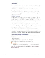
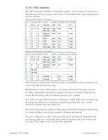
4.20.1 Main Bus
The topology is shown below:
Figure 4-6 I
2
C Main Bus Structure
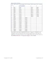
Table 4-26 I
2
C Main Bus Addresses
Slave Device
7-Bit Address
EEPROM DIP Switch 1
0x4E
EEPROM DIP Switch 2
0x4F
Config EEPROM
0x50
SPD EEPROM
0x51
IFC Timings EEPROM
0x58
RTC
0x68
Clock Generator
0x6A
ETI
0x6B
Содержание PPC11A
Страница 1: ...Hardware Reference Manual PPC11A 6U VME Single Board Computer Edition 1 Publication No PPC11A HRM 1 ...
Страница 27: ...Publication No PPC11A HRM 1 Functional Description 27 Figure 4 2 Block Diagram T2081 ...
Страница 113: ...Publication No PPC11A HRM 1 Connectors 113 Figure 6 2 Rear Connector Position ...


