


108 PPC11A 6U VME Single Board Computer
Publication No. PPC11A-HRM/1
5.51.2 Watchdog Prescaler (Low Byte) Register (Offset 0x701)
Together with bit 7:4 of the Watchdog Enable Register, this determines the 12-bit
division ratio used to generate the counting rate of the Watchdog. On the PPC11A,
the input clock is 25 MHz. Program the desired division ratio minus 1, e.g.
0x000 => 25 MHz
0x001 => 12.5 MHz
0x063 (99
D
) => 250 kHz
0x9C3 (2499
D
) => 10 kHz
0xFFF (4095
D
) => 6.1 kHz (approximately)
The default is 0x063 (250 kHz).
This register is locked while the Watchdog is running (bit 0 of the Watchdog Enable
Register is set).
5.51.3 Watchdog Enable Register (Offset 0x702)
Bits 7:4 in this register are locked while the Watchdog is running (bit 0 is set).
Bit 0 in this register is locked according to bit 5 in the
Bits
Description
Default
7 to 4
4 MSBs of the prescaler - see the Watchdog Prescaler (Low Byte) Register 0x0
3 to 1
Reserved
000
b
0
Watchdog enable:
1 = Watchdog enabled
0 = Watchdog disabled
Ensure the Watchdog is fully configured before enabling it
0
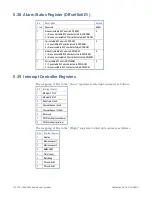
5.51.4 Watchdog Status Register (Offset 0x703)
Bits
Description
Default
7 to 4
Reserved
0x0
3
Warning timer status:
1 = Warning timer running (one ‘minimum’ kick violation detected)
0 = Warning timer not running (no ‘minimum’ kick violation has occurred
in the last two ‘maximum’ periods)
0
2
Warning interrupt output status:
1 = Warning interrupt is being asserted
0 = Warning interrupt is not being asserted
0
1
Warning count reached:
1 = Main counter has reached the warning threshold
0 = Main counter has not reached the warning threshold
0
0
Minimum count reached:
1 = Main counter has reached the minimum threshold
0 = Main counter has not reached the minimum threshold
0
Содержание PPC11A
Страница 1: ...Hardware Reference Manual PPC11A 6U VME Single Board Computer Edition 1 Publication No PPC11A HRM 1 ...
Страница 27: ...Publication No PPC11A HRM 1 Functional Description 27 Figure 4 2 Block Diagram T2081 ...
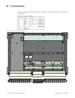
Страница 113: ...Publication No PPC11A HRM 1 Connectors 113 Figure 6 2 Rear Connector Position ...


