


Publication No. PPC11A-HRM/1
Control and Status Registers 101
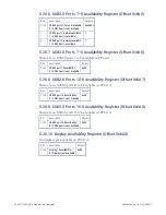
5.36
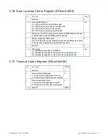
Boot Location Status Register (Offset 0x6CE)
Bit
Description
Default
7
Reserved
0
6 & 5
Active boot ROM location:
11
b
= PPC11A booted from test card (
Abaco only
)
10
b
= PPC11A booted from Alternate area (NOR Flash)
01
b
= PPC11A booted from Recovery area (SPI)
00
b
= PPC11A booted from Main area (NOR Flash)
00
b
4
SPD location. The PPC11A always boots using the SPD EEPROM located on-board
0 = Board booted using SPD EEPROM(s) located on-board
0
3
Ethernet configuration ROM location.
The PPC11A always boots using the Ethernet configuration ROM located on-board
0 = Board booted using Ethernet configuration ROM on-board
0
2
Reserved
0
1 & 0
RCW location:
1x
b
= Board booted using RCW in I
2
C EEPROM
01
b
= Board booted using RCW ‘B’ in FPGA (overlaid over NOR Flash CS0)
00
b
= Board booted using RCW ‘A’ in FPGA (overlaid over NOR Flash CS0)
00
b
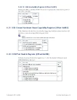
5.37
Thermal Status Register (Offset 0x6D0)
Bit
Description
Default
7
Reserved
0
6
Thermal sensor THERM status:
1 = Thermal sensor THERM output is asserted
0 = Thermal sensor THERM output is not asserted
0
5
Thermal sensor ALERT status:
1 = Thermal sensor ALERT output is asserted
0 = Thermal sensor ALERT output is not asserted
0
4 to 0
Reserved
00000
b
Содержание PPC11A
Страница 1: ...Hardware Reference Manual PPC11A 6U VME Single Board Computer Edition 1 Publication No PPC11A HRM 1 ...
Страница 27: ...Publication No PPC11A HRM 1 Functional Description 27 Figure 4 2 Block Diagram T2081 ...
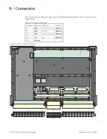
Страница 113: ...Publication No PPC11A HRM 1 Connectors 113 Figure 6 2 Rear Connector Position ...


