Publication No. HRMCP9 Rev. B
Transition Module CTM12 87
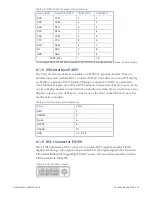
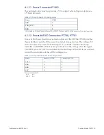
A.1.11 Power Connector P1801
This optional 3-pin connector pr5 V to supply external logic or devices as
2.5” hard drives etc.
Table A-14 Power Connector Pin Assignments
Name
P1801
GND
1
FUSE_VCC
a
2
GND
3
a
+5 V supply via CR9 and fused with max 2 A at CTM12. Don’t exceed 1 A at this connector for normal operation.
A.1.12 Power IN/OUT Connectors P7700, P7701
In case of Hot Swap (insertion or extraction phase) of the CR9 the CTM12 provides
the possibility of switch-off the power to external storage devices. The v5 V
and +12 V between power-in P7700 and power-out P7701 controls a Hot Swap
controller via MOSFETs. The Hot Swap controller cut the voltage when the signal
VCCOFF# is low. VCCOFF is controlled by the Hot Swap at the CR9. In case of over-
current the controller switches off the voltages, too.
Table A-15 Power IN/OUT Connector Pin Assignments
Name
Power In P7700
Power Out P7701
+12 V
1
4
GND
2
3
GND
3
2
+5 V
4
1
Over-current threshold:
+5 V
6 A
+12 V
3 A
Содержание CR9 Series
Страница 24: ...24 CP9 CR9 CT9 Celeron M Pentium M Publication No HRMCP9 Rev B Figure 2 2 Handling the CR9 Board ...
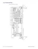
Страница 77: ...Publication No HRMCP9 Rev B Transition Module CTM12 77 Figure A 1 CTM12 Component Locations ...
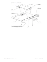
Страница 90: ...90 CP9 CR9 CT9 Celeron M Pentium M Publication No HRMCP9 Rev B Figure B 1 Mount PMC Board to CR9 ...

