Publication No. HRMCP9 Rev. B
Transition Module CTM12 79
A.1.2 Ethernet Interface 10/100/1000BASE-T
P5000 and P5500
The Ethernet interfaces for Rear-IO requires usage of CAT 5 cable for proper
operation with 100/1000BASE-T.
Figure A-2 CTM12 Ethernet Connector Layout
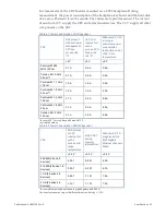
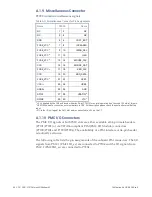
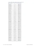
Table A-2 CTM12 Ethernet Connector Pin Assignments
Name 10/100BASE-TX
Name 1000BASE-T
Ethernet1, 2
TxD+
LP_DA+
1
TxD-
LP_DA-
2
RxD+
LP_DB+
3
NC
LP_DC+
4
NC
LP_DC-
5
RxD-
LP_DB-
6
NC
LP_DD+
7
NC
LP_DD-
8
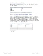
Two LEDs (LED1 and LED2) are integrated in each of the RJ45 connector. These
LEDs indicates the link status of the interface.
Table A-3 CTM12 Ethernet Connector LED
LED1 green
Function
green
General link
blink green/orange
General link with RX/TX activity
LED2 yellow
Function
green
Link 100 Mbit
Orange
Link 1000 Mbit
Содержание CR9 Series
Страница 24: ...24 CP9 CR9 CT9 Celeron M Pentium M Publication No HRMCP9 Rev B Figure 2 2 Handling the CR9 Board ...
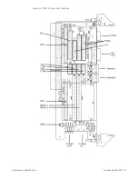
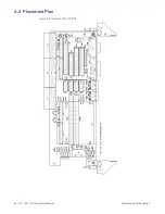
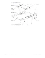
Страница 77: ...Publication No HRMCP9 Rev B Transition Module CTM12 77 Figure A 1 CTM12 Component Locations ...
Страница 90: ...90 CP9 CR9 CT9 Celeron M Pentium M Publication No HRMCP9 Rev B Figure B 1 Mount PMC Board to CR9 ...

