Ascotel® IntelliGate® 150/300 as of I7.9
58
Installation
sy
d-
021
0/1.
7
– I7.
9 – 1
2.
2009
4
Installation
This Chapter tells you the ways in which Ascotel® IntelliGate® 150/300 can be installed
and the conditions to be observed. It also includes the mounting into a 19” rack, the
correct way to connect the earthing, and the power supply. Other topics described in
this Chapter comprise fitting the basic system with system modules, interface cards and
the relevant Wiring Adapters. Finally the Chapter also describes the network and termi-
nal-side connection of the interfaces.
4. 1
System components
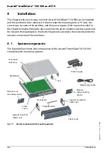
The figure below shows the components of the Ascotel® IntelliGate® A150/300
complete with mounting options.
Fig. 15
System components with mounting options
Cover with
screening
Fan
Power supply
Mains power cable
Plate for rack
mounting variant
Mainboard
Support on right for
cable cover
Cable cover
Plugable label
Screw
covers
Support on left for
cable cover
Plate for
rack-mounting
variant
Front panel


