

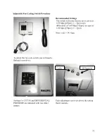


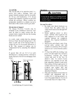


63
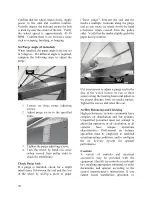
Evaporator Coil
Removal
Evacuate refrigerant from the systems.
Remove the TXV bulbs from the suction
lines. Disconnect the suction and liquid line
copper connections to the evaporator coil.
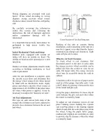
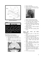
Figure 31 - Evaporator Coil Access
Remove screws attaching filter rack to the
evaporation coil at the front and back of the
coil. It may be necessary to remove the
economizer assembly (if equipped) to access
the screws at the back.
Slide the evaporator coil straight out of the
unit.
It may be necessary to make a vertical cut in
the front flange of the drain pan on either side
of the coil and bend the flange down between
the cuts to remove the evaporator coil.
Reinstallation
Slide the new coil into the unit through the
notch cut in the front of the drain pan.
Re-bend the cut flange back to the original
position, then seal the cuts with polyurethane
caulking.
Attach the filter at the front and back of the
evaporation coil. Reinstall economizer
assembly if necessary.
Connect the suction and liquid copper
connections to the evaporator coil. Reinstall
the TXV bulb on the suction line.
Evacuate the refrigerant system. Weigh in the
nameplate refrigerant charge.
See Adjusting Refrigerant Charge section to
check for proper sub-cooling and superheat
of the refrigerant systems.
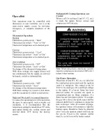
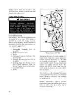
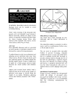
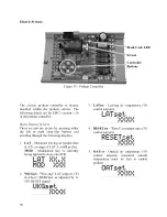
Condenser Fan
Removal
Take off the fan grill by removing the screws
that attach it to the top of the unit.
Electric shock hazard. Shut off all
electrical power to the unit to avoid
shock hazard or injury from rotating
parts.
WARNING
Electric shock hazard. Shut off all
electrical power to the unit to avoid
shock hazard or injury from rotating
parts.
WARNING
Improper installation, adjustment,
alteration, service, or maintenance
can cause property damage, personal
injury, or loss of life. Startup and
service must be performed by a
Factory Trained Service Technician.
WARNING
Содержание RQ NextGen Series
Страница 2: ......
Страница 26: ...26 Figure 3 RQ Cabinet Standard and Power Exhaust Gasket Locations...
Страница 40: ...40 Figure 23 Post Corner Hole Piping Figure 24 Post Back Hole Piping...
Страница 86: ...86 Figure 35 Example 2 6 ton through the Base Gas Piping Note RQ units will only contain one Heat Exchanger...
Страница 88: ...88 Gas Heater Operating Instructions Figure 36 Gas Heater Instructions...
Страница 95: ...95...
Страница 96: ...96...
Страница 105: ...105 Maintenance Log E Coated Coil...
Страница 107: ...107...


