29
RotoClone
®
W
© 2015 American Air Filter Company, Inc. Any use of the text or images
this document contains, without permission of American Air Filter
Company, Inc., is prohibited. RotoClone, AAF, REDClean, REDFiltration,
and Reliable Efficient Durable are registered trademarks of American Air
Filter Company, Inc. d/b/a AAF International.
9.2.6.6
Food Quality RotoClone W
Installation and Operation procedure is the same as shown in Sections 9.2
and 10 of this IOM, with the exception of the requirement for extra water
connections. Additional, valved, 40 psi, water supply connections should be made
for the spray nozzle connections (screwed coupling(s) - see general Arrangement
drawing for location(s)) in the Expansion Chamber and 90° Elbow or Centrifugal
Outlet (if other than the Straight Outlet is supplied). It is recommended that the
valves be opened intermittently, for a brief period, during RotoClone operation and
at shutdown, to facilitate flushing of material that can accumulate and plug the
drains. Frequency and duration of the water spray must be determined individually
for each RotoClone application. (Provision can be made for automatic operation, by
installing solenoid valves, actuated by timers.)
NOTE
: Leaving the water “on” during operation of the RotoClone can result
in water carryover in the exhaust duct; and, will result in excessive water
consumption. An empirically determined timed sequence should be adequate to
keep drains free-flowing, and is the recommended operational approach.
9.2.6.7
Flow Switches for Range Hood and FM Controls
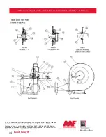
Flow switches are shipped assembled on the external piping assembly, which
is shipped loose. They are referred to as FS-1 and FS-2. Flow switch FS-1 is
connected to the standard inlet nozzle and the impeller flushing (auxiliary) nozzle.
Flow switch FS-2 is connected to the emergency spray nozzle(s). Flow switches are
set at the factory and should not be field adjusted. Each flow switch is set for a
specific flow and is not interchangeable. The flow switches need only be wired up
according to the separate wiring diagram.
9.2.6.8
Solenoid Valves for Range Hood and FM Controls
The solenoid valves (SV-1 and SV-2) are shipped assembled on the external
piping assembly, which is shipped loose. The solenoid valves are identical and
interchangeable; and need only be wired up according to the separate wiring
diagram.
9.2.6.9
Water connection for Range Hood and FM Controls
The “shipped loose” piping assembly is attached to the RotoClone at the two
unions on the end of the loose piping and connecting pieces on the RotoClone.
Connect the water supply line to the strainer on the other end of the RotoClone
piping assembly. It is recommended that a manual shut off valve (supplied by
others) be installed in the supply line to facilitate maintenance on the flow


