26
RotoClone
®
W
© 2015 American Air Filter Company, Inc. Any use of the text or images
this document contains, without permission of American Air Filter
Company, Inc., is prohibited. RotoClone, AAF, REDClean, REDFiltration,
and Reliable Efficient Durable are registered trademarks of American Air
Filter Company, Inc. d/b/a AAF International.
9.2.5.3
Auxiliary Impeller Flushing
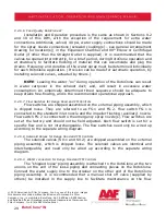
An auxiliary flushing nozzle is supplied with a manual valve or automatic
solenoid valve to provide extra cleaning for the impeller while it coasts down to a
stop after the motor is de-energized.
The automatic solenoid valve option includes a timer/relay in a separate
(shipped loose) box. Refer to the wiring diagram supplied with the unit for
connection directions. The timer/relay is interlocked with the motor starter to open
the solenoid when the “STOP” button is pushed. After the timer runs its preset
time, the solenoid closes, shutting off water to the RotoClone.
NOTE
: The valve should not remain open while the RotoClone
®
is running.
The extra water may cause water entrainment in the exhaust airstream.
9.2.6
Water connections
Arrangement A
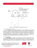
- RotoClone piping may be shipped loose to prevent
damage during shipping. Connect the two lines from the “cross” to the two
connections on the RotoClone inlet. The third outlet from the cross connects to the
pressure gauge supplied and the front leg should be connected to the water supply
line. Supply line should be ¾” size for RotoClone through size 14; 1” size for size
16 RotoClone
®
and larger and designed for supply line water pressures.
Connect the water supply line to strainer located near RotoClone inlet, using
pipe at least as large as the strainer connection. The Solenoid Valve should be
installed between the strainer and cross, and should be wired in parallel with the
RotoClone motor per the wiring diagram supplied with the unit. Solenoid valves
should always be installed with the coil in the top, vertical position. Finished piping
should be per Figure 2. It is recommended that a manual shut-off valve be
installed in the supply line, to be able to do maintenance on the solenoid valve.
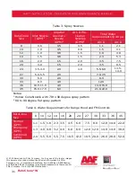
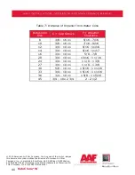
The water connection must be capable of supplying the volume listed in 9.2.6.11,
Table 2 to the spray nozzles at 40 to 60 psi pressure.
Arrangement D
- Instructions same as Arrangement A, strainer located
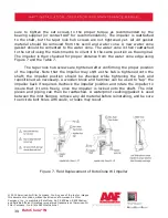
near Pre-cleaner inlet. Refer to Figure 3 for Pressure Gage Installation.
A by-pass connection with manual valve per Figure 4 (both
Arrangement A and D) may be included to safeguard operation of
RotoClone in case of solenoid valve failure or for strainer maintenance.

