User Manual of Digital Video Recorder
14
1.1
Front Panels
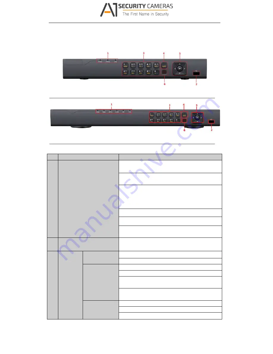
Figure 1. 1
Front Panel of 4/8ch-FT& FA and 4ch-ST Series
Figure 1. 2
Front Panel of 16ch-FT&FA and 8ch-ST series
Table 1. 1
Description of Front Panel
No.
Name
Function Description
1
Status Indicators
POWER: the POWER indicator turns green when NVR is
powered up.
READY: The indicator light is green when the device is running
normally.
STATUS: 1.The light is green when the IR remote control is
enabled; 2.The light is red when the function of the composite
keys (SHIFT) are used; 3. The light is out when none of the
above condition is met/
ALARM: the light is red when there is an alarm occurring.
HDD: the indicator flickers red when HDD is reading/writing.
Tx/Rx: TX/RX indicator flickers green when network
connection is functioning normally.
2
USB Interfaces
Universal Serial Bus (USB) ports for additional devices such as
USB mouse and USB Hard Disk Drive (HDD).
3
Composite
Keys
1/MENU:
Enter numeral “1”;
Access the main menu interface.
2/ABC/F1:
Enter numeral “2”;
Enter letters “ABC”;
The F1 button when used in a list field will select all items in the
list.
In PTZ Control mode, it will turn on/off PTZ light and when the
image is zoomed in, the key is used to zoom out.
3/DEF/F2:
Enter numeral “3”;
Enter letters “DEF”;
The F2 button is used to change the tab pages.
Available from A1 Security Cameras
www.a1securitycameras.com email: [email protected]


