background image

NEED HELP? GIVE US A CALL

 833.232.9711

NEED HELP? GIVE US A CALL

 833.232.9711

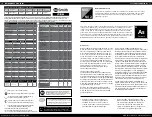
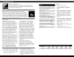
SYSTEM SPECIFICATIONS

16

AOW-4000

Replacement cartridge AOW-4000-CARBON  

and AOW-4000-MEM

System Production     83.93 gpd (317 lpd)

TDS Reduction     96.7% + average

Max TDS     1000 ppm

Max water hardness     26 gpg (450 ppm)

Max Chlorine in water     3.0 ppm

Supply water pH limits     4-10

Drain (reject water) flow     1-2x product flow

Empty storage tank precharge     5-7 psi air (35-48 kPa)

Storage tank capacity     3.2 gallons (12.11 liters)

Supply water pressure limits     40-100 psi (275-689 kPa)

Supply water temp. limits     40-100 degrees F (5-37 degrees C)

Efficiency     37.64%

Recovery     47.66%

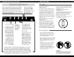
CAPACITY AT VARIOUS WATER PRESSURE LEVELS (WITH 5 PSI PRECHARGE) U.S. GALLONS

TOTAL VOLUME

20 PSI

30 PSI

40 PSI

50 PSI

60 PSI

70 PSI

3.2

1.4

1.8

2.0

2.2

2.4

2.5

NON-POTABLE WATER SOURCES: 

Do not attempt to use this product to make safe drinking water from non-potable water sources. Do not use the system on 

microbiologically unsafe water, or water of unknown quality without adequate disinfection before or after the system. This system is certified for cyst reduction and 

may be used on disinfected water that may contain filterable cysts.

INSTALLATIONS IN THE COMMONWEALTH OF MASSACHUSETTS: 

The Commonwealth of Massachusetts requires installation be performed by a licensed 

plumber and does not permit the use of saddle valves. Plumbing code 248—CMR of the Commonwealth of Massachusetts must be followed in these cases.

Do not use with water that is microbiologically unsafe or of unknown water quality without adequate disinfection before or after the system. 

Systems certified for cyst reduction may be used on disinfected waters that may contain filterable cysts.

Filter is only to be used with cold water. Systems certified for cyst reduction may be used on disinfected water that may contain filterable cysts.

17

Safeguards

•  Use only cold water with filter.

•  If you experience a hose connection  

leak, disconnect and re-seat the hose. 

•  When you use the system for the first time, 

it will flush the preservative solution from 
the RO Membrane and small carbon particles 
from the filter cartridges. This may cause a 
slight discoloration of the water. As you flush 
the system (see startup instructions), this 
discoloration will end.

•  It is possible for the unit to become 

contaminated if it is not operated for a long 
period of time. To prevent this from happening, 
the system will perform an automatic flush if it 
sits idle for three days.

•  Disconnect the power and shut off the water 

supply before fixing any leaks in the system.

•  Do not allow the system to freeze. See 

deactivating system in this manual.

Specifications – Qualified System Performance
Because the performance of a Reverse Osmosis 
Membrane is highly dependent upon pressure, 
temperature and Total Dissolved Solids (TDS),  
the following should be used for comparison  
purposes only.

Industry standards measure RO Membranes  
performance with no back pressure on the product 
water, at 60 psig (414 kPa) and 77°F (25°C). Further 
conditions on the above are 250 ppm TDS and a 
30.6% recovery rate. Production rate and TDS  
reduction figures are for a new Membrane that 
has been rinsed for 24 hours. The production rate 
of a new Membrane can decrease by 10% per year 
or more, depending upon the scaling and fouling 
tendencies of the Feed Water.

TDS Reduction measured at 50 psi, 77°±2°F,  
and 717 mg/l TDS per NSF/ANSI Standard 58.

Efficiency rating is the percentage of the influent 
water to the system that is available to the  
user as reverse osmosis treated water. This  
measurement is taken under operating  
conditions that approximate typical daily usage.

Recovery rating is the percentage of the influent 
water to the membrane portion of the system that  
is available to the user as reverse osmosis treated 
water when the system is operated without a  
storage Tank or when the Storage Tank is bypassed.

Flow rate and output are determined  
by 3 factors:

1

  Incoming water temperature

Total dissolved solids (TDS) present in  

  supply water

Incoming water pressure

Lower temperatures are directly proportional to 
slower flow rate. All membranes are tested at 77°F. 
Incoming water temperature should not exceed 
100°F. The RO Filter System should also not be 
installed in a location susceptible to freezing. The 
more TDS in the supply water, the more filter time 
is required. Incoming TDS should not exceed 1000 
ppm. Higher water pressure enables a higher flow 
rate. Pressure must be above 20 psi for proper sys-
tem operation. The system includes an  
integral booster.

Cleaning

To clean your filter unit, wipe down the  
exterior with a damp cloth. 

Содержание Pro AOW-4000

Страница 1: ...NER S MANUAL Use this owner s manual to reference installation troubleshooting and filter replacement information If you need help or have a question we ve got you covered Give us a call at 833 232 97...

Страница 2: ...ther manufacturers will also void your warranty Please visit www aosmith com wholesale for replacement parts Installation must comply with state and local ordinances A O Smith is not liable for conseq...

Страница 3: ...those you can see smell and taste and those you can t with no chemical additives Whatever your water needs from hydration to cooking early morning coffee smoothies or soup you will now have filtered w...

Страница 4: ...stem Manifold Remineralizer and Tank into the under sink cabinet or desired location to ensure adequate space and proper positioning 1 This system is designed to be installed under the sink but wherev...

Страница 5: ...semble the quick connect tubing adapter to the faucet base threads 1 Identify drain outlet location Do not install the drain connector onto the same drainpipe as the garbage disposal If drain line mus...

Страница 6: ...d with two clear covers on the ends of the membrane These covers are only included to protect the Membrane seals during shipping and they should be removed and disposed of before installation 2 Discon...

Страница 7: ...Tank connection 1 4 white tubing Use a length of 1 4 white tubing to connect the System Manifold to the Storage Tank Insert one end of the tubing to the tank fitting on the System Manifold and the ot...

Страница 8: ...he system will perform a brief startup flush and then return to normal service The system monitors the life of the five filter elements and notifies you when they need to be replaced The display shows...

Страница 9: ...idges can lead to contamination that can cause an unsafe condition when the system restarts Replace with new filter cartridges before restarting the system Check that both O rings are assembled to the...

Страница 10: ...ontrile 0 024 0 0006 98 dichloroacetontrile 0 0096 0 0002 98 trichloroacetontrile 0 015 0 0003 98 haloketones HK 1 1 dichloro 2 propanone 0 0072 0 0001 99 1 1 1 trichloro 2 propanone 0 0082 0 0003 96...

Страница 11: ...see startup instructions this discoloration will end It is possible for the unit to become contaminated if it is not operated for a long period of time To prevent this from happening the system will...

Страница 12: ...ons upon payment of 9 50 for shipping and handling per incident How to get service To receive service under this warranty you must contact A O Smith at 833 232 9711 or watertreatmentpro aosmith com wi...

Страница 13: ...lta una pieza o alguna est da ada ll menos para avisarnos al 833 232 9711 No intente instalar el filtro Herramientas recomendadas para la instalaci n N CINTA DE TEFL N O DETECTOR DE FUGAS P LLAVES PAR...

Страница 14: ...omo para que no se necesiten m s de 5 m 15 pies de tubo entre el sistema de OI y la llave El sistema de OI no se debe colocar a m s de 3 m 10 pies bajo la llave Una distancia o diferencia excesiva de...

Страница 15: ...apriete en exceso ADAPTADOR DE ALIMENTACI N DE AGUA V LVULA DE CIERRE DEL TANQUE 25 PASO 4 Instalaci n del conector de drenaje 1 Identifique la ubicaci n de la salida de drenaje No instale el conecto...

Страница 16: ...lave Deslice el escudo con la junta sobre la tuber a de drenaje hasta que quede asentado contra la llave 6 Coloque las tuber as en el orificio de instalaci n e inserte la llave en el orificio con el l...

Страница 17: ...mbrana Estas cubiertas solo se incluyen para proteger los sellos de la membrana durante el env o y se deben retirar y desechar antes de la instalaci n 2 Desconecte el tubo blanco del conector de conex...

Страница 18: ...1 4 para conectar el colector del sistema al tanque de almacenamiento Inserte un extremo del tubo en el conector del tanque del colector del sistema y el otro extremo en la v lvula de cierre de la par...

Страница 19: ...ando y llenar el tanque de almacenamiento con agua purificada Mientras la unidad est en funcionamiento vuelva a verificar el sistema para encontrar fugas PROCEDIMIENTO DE ARRANQUE INICIAL 1 Cierre la...

Страница 20: ...til del filtro de un cartucho despu s de que se reemplaza Para restablecer la vida til de un cartucho presione el bot n Select hasta que el cono del cartucho de filtro deseado parpadee Cuando haya sel...

Страница 21: ...00001 99 heptachlor epoxide 0 0002 0 0107 0 0002 98 hexachlorobutadiene 0 044 0 001 98 hexachlorocyclopentadiene 0 05 0 060 0 000002 99 lindane 0 0002 0 055 0 00001 99 methoxychlor 0 04 0 050 0 0001 9...

Страница 22: ...sistema reduce el ars nico pentavalente pero es posible que no elimine otras formas de ars nico Este sistema se debe usar en suministros de agua que contengan un cloro libre detectable residual en la...

Страница 23: ...S EN EL ESTADO DE MASSACHUSETTS El Estado de Massachusetts exige que la instalaci n la realice un plomero con licencia y no permite el uso de v lvulas de silla Se debe cumplir con el C digo de plomer...

Отзывы: