


39
board and is not covered under the limited warranty.
connecting an external supervisory control
The enable/disable circuit is accessed from the CCB’s J6 plug
inside the CCB enclosure, see Figure 3 on page 8 to locate the
CCB enclosure. From the factory there is a short (black) jumper
wire installed between pins 8 and 11 of the J6 plug, see Figure
61 on page 63 to locate the J6 plug.
install field wiring to the enable/disable circuit:
1.
Turn off power at the water heater’s on/off switch and the
breaker that supplies power to the appliance.
2.
Locate the CCB enclosure.
3.
remove the screws from the CCB enclosure cover and
carefully open the CCB enclosure. Note how strain relief for
the wiring is provided between the cover and enclosure along
one edge.
4.
Activate the enable/disable circuit; locate the S1 dipswitch on
the CCB, see Figure 61 on page 63.
• Toggle S1 dipswitch #2 to the open position.
• Toggle S1 dipswitch #3 to the open position.
5.
Locate the black jumper wire between pin 8 and 11 on the
CCB J6 plug, see Figure 61 on page 63 and Figure 62 on page
6.
Cut the black jumper wire in the middle.
7.
Strip approximately 1/2 inch of insulation from the two ends
of the black jumper wire.
8.
Using wire nuts connect two field supplied control wires to
the two ends of the black jumper wire. Wrap electrical tape
around the wire nut connections.
9.
Thread the control wires out of the CCB enclosure with the
other wiring and carefully replace the CCB enclosure cover.
Ensure all wiring is routed through the indented area provided
for strain relief. Ensure no wiring is being pinched.
10.
reinstall the CCB enclosure cover screws and tighten.
11.
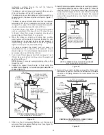
route the control wires inside the junction box on the top of
the water heater, see Figure 3 on page 8 to locate the junction
box. Use an available knock-out to route the wires inside the
junction box.
12.
install field supplied control wiring and conduit as required
by national and local codes between the water heater’s
junction box and the external supervisory control. Connect
the wiring from the external control to the control wires inside
the junction box using wire nuts and electrical tape.
13.
Connect the control wiring to a set of dry contacts on the
external control. Follow the control manufacturers instructions
for making connections.
14.
restore power to the water heater.
note:
Whenever the external control opens the set of dry
contacts used, heating operation will be disabled. Whenever
the external control closes the set of dry contacts used, heating
operation will be enabled. A diagonal line and circle appears
over the thermometer icon on the control system’s display when
heating operation is disabled. See the Status icons descriptions
note:
Ensure the water heater is protected from freezing
temperatures when heating operation is disabled. Damage to
the water heater caused by freezing temperatures is not covered
under the limited warranty.
electrical wiring
All electrical work must be installed in accordance with the
National Electrical Code, ANSi/NFPA 70 or the Canadian
Electrical Code, CSA C22.1 and local requirements.
When installed, the water heater must be electrically grounded
in accordance with local codes or, in the absence of local codes,
with the National Electrical Code, ANSi/NFPA 70 or the Canadian
Electrical Code, CSA C22.1.
if any of the original wire as supplied with the water heater must
be replaced, it must be replaced with 105°C rated wiring or its
equivalent, except in the burner housing. in this case use 200°C
rated wire must be used.
power supply connections
read the requirements for the Power Supply on page 13 before
connecting power.
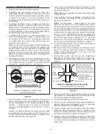
correct polarity:
The water heater’s control system is polarity sensitive and
will lock out and disable heating operation if the polarity of the
power supply is reversed. The control system will display the
“AC reversed” Fault message on the LCD. The 120 VAC hot
wire from the power supply must connect to the black wire in the
junction box and the 120 VAC neutral wire must connect to the
white wire in the junction box for correct polarity.
Power supply connections must be made as follows:
1.
Ensure the power supply is turned off at the breaker or
disconnect switch.
2.
remove the junction box cover. See Figure 3 on page 8 for
junction box location.
3.
Connect the 120 VAC hot wire from the power supply to the
black wire in the junction box on top of the water heater with a
properly sized wire nut. Wrap electrical tape around the wire
nut and wire end. See wiring diagrams Figure 62 on page 64
4.
Connect the 120 VAC neutral wire from the power supply to
the white wire in the junction box. Wrap electrical tape around
the wire nut and wire end. See wiring diagrams Figure 62 on
page 64 and Figure 63 on page 65.
5.
Connect the ground wire from the power supply to the
grounding lug inside the junction box. See wiring diagrams
Figure 62 on page 64 and Figure 63 on page 65.
6.
replace the junction box cover when connections are
complete.
note:
Do not apply power to the water heater before installation
is complete and the water heater is filled with water.
enaBle/disaBle circuit
The water heaters covered in this manual are equipped with
an enable/disable circuit for use with field supplied external
supervisory controls such as time clocks or building Building
management Systems. The enable/disable circuit may be used
to disable heating operation during periods when the building is
unoccupied or there is no demand for hot water.
To use the enable/disable circuit it must first be activated by
configuring the S1 dipswitch on the water heater’s CCB (central
control board), see Figure 61 on page 63. Field supplied wiring
is then installed between the water heater’s CCB and a set of
“dry contacts” (no voltage or load) on the field supplied external
control.
note:
The water heater’s enable/disable circuit is a switching
circuit only: Do not apply external voltage or connect any load
(iE: relay coil) to this circuit. This will damage the CCB circuit
Содержание 101 Series
Страница 75: ...75...


