manualshive.com logo in svg
background image


PinVision for Twilight Zone 

Installation Manual 


Содержание PinVision for Twilight Zone

Страница 1: ...PinVision for Twilight Zone Installation Manual ...

Страница 2: ... Contents Part Quantity Controller Board 1 12V Power Adapter 1 DC Power Extension Cable 1 HDMI Cable 1 Display Power Harness 1 Power Sensing Harness 1 Wood Screws Hex Head 2 10 Wood Screws Phillips Pan Head 2 ...

Страница 3: ...Mounting Brackets 2 Backboard Unit 1 34 Pin Data Cable Adapter 1 Threaded Aluminum Standoffs 2 ...
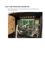
Страница 4: ...nt surface scratches and dust during shipping 1 Remove the 5 black wood screws securing the impact shield to the backboard 2 Remove protective paper film on both sides of the plastic 3 Secure the impact shield back to the back board using the same screws BE CAREFUL Do not over tighten screws as that could lead to cracking ...

Страница 5: ...Step 1 Install The Interactive Controller Card 1 Open the game s backbox and unplug the ribbon cable at J601 on the DMD board and J506 on the sound board ...

Страница 6: ...2 Remove the existing machine screws at the top of the sound board center and replace with the included aluminum standoffs as shown below ...

Страница 7: ...the included 34 pin ribbon cable adapter and plug it into J506 on the sound board as shown below The red stripe should be facing up and the notch in the cable adapter should be pointing to the left of the game ...

Страница 8: ...4 Plug the other end of the ribbon cable into the J2 port on the Interactive Display Controller board as shown below ...

Страница 9: ...5 Mount the Interactive Display Controller board to the sound board using the two machine screws removed earlier and mounting the board to the standoffs you just installed ...

Страница 10: ...e DC extension cable and plug the male end into the barrel jack on the Interactive Display Controller board as shown below Drop the remaining slack down through the backbox wire routing hole and into the cabinet ...

Страница 11: ...cable and insert the mini end into the controller board as shown below Note that the cable will actually be inserted upside down If needed gently remove the raspberry pi from the controller board to make this connection and reattach ...

Страница 12: ...ow The red wires should be located toward the bottom Connect the original cable into the Z connector URGENT NOTE ABOUT CABLE ORIENTATION Note that some cables may not have ramped connectors make sure that the connector plugs into the WPC sound board with the black or gray cables on top and red on bottom as shown above ...

Страница 13: ...ve Display Controller board at J12 as shown below URGENT NOTE ABOUT CABLE ORIENTATION Note that some cables may not have ramped connectors When connecting the sensing cable shown above make sure the connector is plugged in so that the red wire is on the LEFT ...

Страница 14: ... remaining slack through the bottom hole in the backbox and into the cabinet This will power our display URGENT NOTE ABOUT CABLE ORIENTATION When connecting the display power cable make sure the connector is plugged into the controller board so that the RED wire is on the LEFT and the black or gray wire is on the RIGHT ...

Страница 15: ...14 Reattach the sound data ribbon cable to the 34 pin ribbon cable adapter as shown below Reconnect the original ribbon cable to J601 on the DMD board ...

Страница 16: ......

Страница 17: ...s live AC voltages You must power off and unplug the game prior to installing this mod The existing backboard in WPC machines is secured to the playfield via five phillips head wood screws at the back underneath the playfield 1 First place the playfield into the upright service position as shown below be sure to remove the balls from the trough first ...

Страница 18: ...kboard screws at the back of the playfield as shown below Use a phillips head screwdriver to remove the 5 screws Hold the backboard when removing the final screw to mitigate the risk of the board falling into the cabinet ...

Страница 19: ...hat drill into the backboard through the playfield we ve simplified the process by using two angle L brackets to secure the backboard to the playfield using the existing screw holes 1 Locate the far left and right mounting holes at the rear of the playfield shown in green below ...

Страница 20: ...nd of the bracket should be on the bottom side of the playfield Do not overtighten the bracket screws Note The slots on the brackets allow for adjustments to backboard display positioning Do not position the backboard too far back into the cabinet as it can and most likely will collide with the game s wire harness running to the backbox ...

Страница 21: ... the included power supply into the game s service outlet as shown below If no service outlet is available an external outlet will need to be used 4 Plug the DC power adapter barrel plug into the female end of the extension cord you dropped through from the backbox previously ...

Страница 22: ...Step 4 Install the Backboard Display 1 Lower the playfield into the lower service position down but resting on the front of the cabinet ...

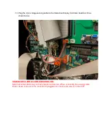
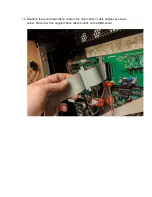
Страница 23: ...2 You should see the brackets as shown below ...

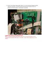
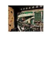
Страница 24: ...3 Gently lower and rest the backboard display against the brackets as shown below ...

Страница 25: ...lignment of the board is centered from the cabinet walls With an electric screwdriver with either a nut driver bit or a flat head bit drive both screws into the rear of the display panel via the top hole of the mounting bracket ...

Страница 26: ...ightly loosening the screws on the L brackets beneath the playfield Afterward connect the HDMI cable and the male DC power cable that you dropped into the cabinet from the backbox in previous steps These connectors are all the way to the right on the board behind the display ...

Страница 27: ...6 Gently slide the playfield back into the cabinet and check the alignment again If everything is good proceed to power the game on ...

Отзывы: