background image

27 


5.


Product information


5.1.


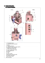
Functional description


1. 

Cooling fan cover 

2. 

Automatic pressure sensor 

3. 

Motor  

4. 

Impeller chamber  

5. 

Automatic pressure by-pass switch 

6. 

Exhaust air outlet tubing 

7. 

Waste water outlet hole 

8. 

Auto by-pass drain tubing 

9. 

Waste water inlet 

10. 

Inverter 

11. 

Filter  

12. 

Filter housing 

13. 

Main power switch (on-off) 

14. 

Inverter cooling fan 

15. 

Main power cord 

16. 

Consensus


Содержание RAIN2+

Страница 1: ...AIN4 Manuale di installazione ed uso Installation User Manual 4tek S r l Viale Dell Industria 66 20037 Paderno Dugnano MI ITALY Tel 39 02 91082211 Fax 39 02 91084668 P IVA C F 05133430966 www 4 tek it riccardo 4 tek it gabriella 4 tek it stefano 4 tek it ...

Страница 2: ...o 7 3 4 Sballaggio 7 3 5 Montaggio 7 3 6 Installazione 7 3 7 Come collegare il tubo di aspirazione 9 3 8 Come collegare il tubo di scarico 9 3 9 Come collegare il tubo di espulsione dell aria 9 3 10 Collegamento elettrico 10 3 11 Evitare il rischio di folgorazione 10 4 Funzionamento 10 4 1 Check list prima di mettere in esercizio la macchina 10 5 Informazioni sul prodotto 11 5 1 Componenti 11 5 2 ...

Страница 3: ...Introduction 23 3 3 Transport storage conditions 23 3 4 Unpacking 23 3 5 Mounting 24 3 6 Installation location 24 3 7 Suction inlet hose connection 25 3 8 Waste outlet hose connection 25 3 9 Exhaust air hose connection 25 3 10 Electrical connection 26 3 11 Electrical shock hazard 26 4 Operation 26 5 Product information 27 5 1 Functional description 27 5 2 Specification of each products 28 6 Mainte...

Страница 4: ...nza delle istruzioni posso causare problemi alle persone CAUTION Caution Attenzione errori nell osservanza delle istruzioni possono causare danni alla macchina ed alle macchine ad essa vicine Le seguenti etichette sono visibili sulla macchina Caution Warning messaggio di attenzione all interno del manuale Folgorazione etichetta applicata sulla macchina Superficie calda etichetta applicata sulla ma...

Страница 5: ...lla valvola potrebbe causare il surriscaldamento del motore ed il suo incendio Mai inserire le dita o qualsiasi altro oggetto nelle prese d aria della macchina Utilizzare la macchina solo in zone ventilate Tutti i motori elettrici hanno una ventola di raffreddamento WARNING Non mettere in funzione la macchina in luoghi contenenti sostanze infiammabili o esplosive Accertarsi di aver identificato co...

Страница 6: ...estato in base a quanto previsto dalla norma IEC 60601 1 2 per i dispositivi medici sulla compatibilità elettromagnetica in ambienti medicali Il dispositivo genera usa e può emettere energia a radio frequenza quindi se non installato ed utilizzato secondo quanto previsto dal manuale di istruzioni può causare interferenze con i dispositivi installati nella stessa area Se il dispositivo dovesse crea...

Страница 7: ...istributore si consiglia di far riferimento alla matricola della macchina per una identificazione più rapida 3 5 Montaggio Il prodotto è dotato di piedini in gomma I piedini in gomma sono fondamentali in quanto limitando le vibrazioni aiutano ad abbassare il livello sonoro 3 6 Installazione Si consiglia di installare il sistema di aspirazione in un luogo pulito asciutto e ventilato Si raccomanda d...

Страница 8: ...Inoltre utilizzare tubi aventi Ø40mm L utilizzo di tubature in plastica potrebbe causare l aumento della temperatura dell aria e dell acqua di scarico Si raccomanda quindi l uso di tubi in metallo o comunque resistenti al calore per i primi 1 5 2 5 metri a partire dalla valvola di scarico dell aria dal lato dello scarico Inoltre i tubi devono essere etichettati con la dicitura PERICOLO RISCHIO DI ...

Страница 9: ...l nastro in teflon 3 8 Come collegare il tubo di scarico Utilizzare sempre un tubo spiralato con Ø20mm interno Collegare il tubo al foro di scarico ruotando in senso orario Serrarlo con fascette metalliche o nastro in teflon Assicurarsi di essere sempre ad un altezza superiore a quella discarico 3 9 Come collegare il tubo di espulsione dell aria Ruotare a sx il raccordo di serraggio del tubo di sc...

Страница 10: ...llegare la macchina Installare la macchina in ambienti in cui non possa venire a contatto con acqua o altri liquidi Installare la macchina in ambienti chiusi Collegare la messa a terra della macchina La non osservanza di queste indicazioni potrebbe causare la morte incendi o folgorazione 4 Funzionamento 4 1 Check list prima di mettere in esercizio la macchina Controllare che non ci sia alcun eleme...

Страница 11: ...ter 3 Motore 11 Coperchio filtro 4 Girante 12 Alloggiamento del filtro 5 Interruttore per disinserire il sensore di pressione automatico 13 Interruttore generale on off 6 Scarico dell aria espulsa 14 Ventola dell inverter 7 Scarico dell acqua espulsa 15 Cavo di alimentazione 8 Tubo per disinserire lo scarico automatico 16 Consenso ...

Страница 12: ... 63Kw Inverter 0 75Kw Assorbimento 3 5 50Hz 4 65Hz Rotazione motore elettrico 0 3980 giri min Vuoto preimpostato 200mbar Vuoto massimo 370mbar Posti lavoro sino a 2 Peso 32Kg Dimensioni L x P x H 41 x 51 x 61cm Livello sonoro 59dB Dimensionamento Tubi Aspirazione 38mm interno Scarico liquidi 19mm interno Espulsione aria 38mm interno ...

Страница 13: ...zione motore elettrico 3740 giri min Vuoto preimpostato 200mbar Vuoto massimo 370mbar Posti lavoro sino a 4 Peso 36Kg Dimensioni L x P x H 41 x 51 x 63cm Livello sonoro 61dB Dimensionamento Tubi Aspirazione 38mm interno Scarico liquidi 19mm interno Espulsione aria 38mm interno Inverter 1 Modalità sensore di pressione automatico Il potere aspirante della macchina è regolato automaticamente dal sens...

Страница 14: ...llo di vuoto A questo punto contattare il centro assistenza per ripristinare il sensore di pressione 3 Modificare la frequenza preimpostata 55Hz portandola ad un valore inferiore 1 Premere il pulsante MODE 2 Quando il paramentro Pr è 0 girare la manopola in senso orario sino a che il parametro Pr divenga 5 3 Premere il pulsante SET ed apparirà il valore 55 Hz 4 Girare la manopola in senso orario s...

Страница 15: ...adualmente e si ferma definitivamente dopo 20sec di inattività In questo modo si elimina qualsiasi residuo di sangue o acqua all interno delle tubature 6 Manutenzione 6 1 Pulizia del filtro di aspirazione Estrarre in filtro ruotando in senso antiorario Pulire il filtro mettendolo sotto l acqua corrente per eliminare possibili residui Si raccomanda di pulire il filtro almeno 2 volte al mese affinch...

Страница 16: ...potrebbe causare dei riflussi di acqua nel motore di aspirazione e quindi la sua rottura 7 Smaltimento CAUTION Dopo parecchi anni di utilizzo la macchina potrebbe contaminarsi Si prega di informare la società che si occuperà del suo smaltimento in modo che possa prendere le dovute precauzioni I componenti in plastica non contaminati possono essere riciclati come plastica La scheda elettronica e gl...

Страница 17: ... la girante e pulirla La macchina scalda troppo Collegamento elettrico errato Bassa tensione di alimentazione Il foro di aspirazione è ostruito La pressione o il livello di vuoto è troppo alto Controllare i collegamenti Controllare la tensione di alimentazione Pulire il filtro di aspirazione Installare una valvola di regolazione del vuoto un manometro ed un vuotometro La potenza aspirante è bassa ...

Страница 18: ... informi per iscritto 4TEK S r l Fax 39 02 91084668 or E mail stefano 4 tek it riccardo 4 tek it gabriella 4 tek it o il rappresentante di zona In ogni caso si ricorda che il trasporto della macchina da riparare è a carico del cliente e che il costo del trasporto non è incluso nel costo di riparazione La garanzia non si estende a difetti dovuti ad errata manutenzione negligenza e o danni accidenta...

Страница 19: ...3 RAIN4 Installation User Manual 4tek S r Viale Dell Industria 66 20037 Paderno Dugnano MI ITALY Tel 39 02 91082211 Fax 39 02 91084668 P IVA C F 05133430966 www 4 tek it riccardo 4 tek it gabriella 4 tek it stefano 4 tek it ...

Страница 20: ... Introduction 23 3 3 Transport storage conditions 23 3 4 Unpacking 23 3 5 Mounting 24 3 6 Installation location 24 3 7 Suction inlet hose connection 25 3 8 Waste outlet hose connection 25 3 9 Exhaust air hose connection 25 3 10 Electrical connection 26 3 11 Electrical shock hazard 26 4 Operation 26 5 Product information 27 5 1 Functional description 27 5 2 Specification of each products 28 6 Maint...

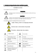
Страница 21: ... given where failure to observe instruction could result in injury to people CAUTION Cautions are found where failure to observe the instruction could result in damage to the equipment associated equipment and process The following symbols of warning will be found on the pump Caution Warning Refer to accompanying documents Electrical shock Attached label at the products Hot surface Attached label ...

Страница 22: ...y identify intake and discharge before using Protect unit from contaminants and moisture WARNING Remove plug from air exhaust port before using 2 2 Caution to reduce risk of electrical shock Do not disassemble Disassembly or attempted repairs if accomplished incorrectly can create electrical shock hazard Refer servicing to qualified service agencies only Do not use this product in or near area whe...

Страница 23: ...the receiving device Increase the separation between the equipment Connect the equipment into an outlet on a circuit different from that to which the other device s are connected Consult that manufacturer or field service technician for help 3 Installation notes 3 1 Environmental conditions The pump is rated for indoor use only Maximum altitude 2000 meters Operating temperature range 10 C to 40 C ...

Страница 24: ...d area Please be sure not to block the ventilation ports located on the motor housing The unit should be placed where the surrounding temperature remains between 10oC and 40oC 50oF and 104oF Always check to insure the location chosen is protected from direct or indirect moisture contact Place suction outlet valve higher position than drainage to prevent backflow problem Hose connection Diagram of ...

Страница 25: ...e PVC flexible spiral hoses with integrated spiral or hoses of equivalent material 3 7 Suction inlet hose connection Remove the cover of suction inlet and push in tubing connector in the inlet hole Connect suction inlet hose Ø40mm spiral hose at tubing connector and tighten with teflon insulation tape 3 8 Waste outlet hose connection Always use spiral hose with Ø20mm interior Connect hose to the o...

Страница 26: ...e installing this product Install the system in a location where it will not come in to contact with water or other liquids Install the system in a location protected from the weather Electrically ground the system Failure to follow these instructions can resulting death fire or electrical shock 4 Operation Check list before start up the system Check if there is any foreign material in the cooling...

Страница 27: ...sensor 3 Motor 4 Impeller chamber 5 Automatic pressure by pass switch 6 Exhaust air outlet tubing 7 Waste water outlet hole 8 Auto by pass drain tubing 9 Waste water inlet 10 Inverter 11 Filter 12 Filter housing 13 Main power switch on off 14 Inverter cooling fan 15 Main power cord 16 Consensus ...

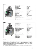
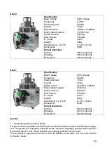
Страница 28: ...Electrical Power 0 63Kw Inverter 0 75Kw Rated Current 3 5 50Hz 4 65Hz Motor rotation speed 0 3980 rmp Setted vacuum 200mbar Max Vacuum 370mbar N Chairs Until 2 Weight 32Kg Dimensions L x P x H 41 x 51 x 61cm Noise level 59dB Hose Dimensions Suction 40mm internal Drainage 20mm internal Exhaust air 40mm internal ...

Страница 29: ... 2 2Kw Rated current 4 5 50Hz 5 65Hz Motor rotation speed 3740 rmp Setted vacuum 200mbar Max vacuum 370mbar N Chairs until 4 Weight 36Kg Dimensions L x P x H 41 x 51 x 63cm Noise level 61dB Hose Dimensions Suction 40mm internal Drainage 20mm internal Exhaust air 40mm internal Inverter Automatic pressure sensor Mode Suction power is regulated automatically by automatic pressure sensor according to ...

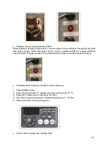
Страница 30: ...y sufficient vacuum power Please contact your authorized technician to replace pressure sensor Changing fixed frequency 55Hz to lower frequency 1 Press MODE button 2 When Pr parameter 0 display turn dial clock wise to Pr 5 3 Press SET button then it will show 55 Hz 4 Turn dial counter clock wise to desirable frequency 0 55 Hz 5 Press set button to fix the frequency Check current Amp and Voltage Va...

Страница 31: ...20 seconds It reduces any remaining residue of water blood in the suction hose 6 Maintenance 6 1 Cleaning suction inlet filter Pull out filter part from machine in counter clockwise direction of cover Clean filter in running water for removing particle or debris Recommending it cleaned at least twice per month for avoiding reduction of suction power Re connect filter CAUTION If the machine install...

Страница 32: ... CAUTION DO NOT use a foaming cleaning It causes backflow of water to the suction motor and can damage it 7 Disposal CAUTION This product may be contaminated after using years Please make the disposal organization aware of this in order that they can take the proper safety actions Uncontaminated plastic components of the product may be recycled The built in electric circuit board and other electri...

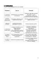
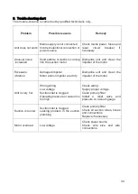
Страница 33: ...er of the motor Excessive vibration Damaged impeller Motor and or impeller are dirty Dismantle unit and clean the impeller of the motor Unit is very hot Wrong wiring Low voltage Suction inlet is clogged Operating pressure or vacuum is too high Check wiring Supply proper voltage Clean primary filter Install a relief valve and pressure or vacuum gauge Suction is too low Suction inlet is clogged Leak...

Страница 34: ...gabriella 4 tek it or to a representative in his country Customer is responsible for freight charges to 4TEK S r l in all cases This warranty does not extend to any goods or parts which have been subjected to misuse lack of maintenance neglect damage by accident or transit damage 4TEK S r l is not responsible or liable for indirect or consequential damages of any kind however including but not lim...

Страница 35: ...35 ...

Страница 36: ...36 M R12 rev 02 4th May 2019 ...

Отзывы: