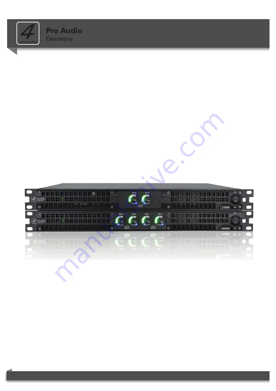
background image

4-acoustic

.com

SX-Series Operation Manual REV01 0820

Pro Audio


Germany

4

acoustic

Operation Manual

SX-25000


|


SX-44000


|


SX-46000

Содержание SX-25000

Страница 1: ...4 acoustic com SX Series Operation Manual REV01 0820 Pro Audio Germany 4 acoustic Operation Manual SX 25000 SX 44000 SX 46000...

Страница 2: ...Page 9 7 2 SX 25000 Back Panel Page 9 7 3 SX 44000 SX 46000 Front Panel Page 10 7 4 SX 44000 SX 46000 Back Panel Page 10 7 5 SX 25000 DIP Switch Setting Page 11 7 6 SX 44000 SX 46000 DIP Switch Setti...

Страница 3: ...When the unit is installed in a cabinet or a shelf make sure that it has sufficient space on all sides to allow for proper ventilation 50 cm from the front and rear Ventilation Openings To completely...

Страница 4: ...in any way such as power supply cord or plug is damaged liquid has been spilled or objects have fallen into the apparatus the apparatus has been exposed to rain or moisture does not operate normally...

Страница 5: ...f treatment and recovery of electronic equip ment WEEE in order to reduce the amount of WEEE that is being disposed of in land fill site All of our products are marked with the WEEE symbol this indica...

Страница 6: ...ma and theme parks For safe installation and use of this amplifier please study this operation manual thoroughly to become acquainted with the basic configuration and control options available It prov...

Страница 7: ...re they are offered for recycling 4 1 Unpacking Checking For Shipping Damage 5 1 Installing Your Amplifier Before you begin make sure your amplifier is disconnected from the power source The common in...

Страница 8: ...ON 2 1 ON ON 2 1 ON ON 2 1 ON ON 2 0V 1 4V 1 0V 0 775V PARALLEL 44 50 483 32 438 32 385 12 50 ON OFF CH A CH B CH C CH D PARALLEL BRIDGE PARALLEL BRIDGE PROTECT PROTECT ON 1 2 3 4 5 6 7 8 9 10 MAINS...

Страница 9: ...put 3dB green 3dB below rated output 1dB green 1dB below rated output 0dB yellow rated output 1dB yellow 1dB over rated output 2dB yellow 2dB over rated output Clip red clipped signal detected at Inpu...

Страница 10: ...inates when the amplifier output channel has stopped operating C Power CH 1 2 and CH 3 4 Indicator green Illuminates when power supply is activated for channel pair 1 2 or 3 4 D Bridge Mode CH 1 2 and...

Страница 11: ...2 1 ON ON 2 1 ON ON 2 1 ON ON 2 1 ON ON 2 0V 1 4V 1 0V 0 775V PARALLEL The two channel model SX 25000 has control options for the Input sensitivity and the signal input mode of the XLR input sockets C...

Страница 12: ...ut Socket CHA connected CHB Input Socket CHB connected CHC Input Socket CHD connected CHD 5 6 Input Socket CHA connected CHA 7 8 9 10 Input Socket CHA connected CHB Input Socket CHB connected CHC Inpu...

Страница 13: ...ercon plug with the amplifier as shown in figure 8 1 before connecting the power cord with the Mains supply The Powercon Connector should be never connect or disconnect if the amplifier is switched on...

Страница 14: ...and noise being induced in the signal cables gets higher as closer this two groups of cable are To prevent the risk of overdriving and damage transducers always turn off the entire sound system befor...

Страница 15: ...ting with banana plugs spade lugs or bare wire SX 25000 only Select the appropriate size of wire based on the distance from amplifier to speaker Distance Wire Size up to 10 Meter 1 5mm up to 30 Meter...

Страница 16: ...re 9 1 Only SX 25000 Connect Channel 1 loudspeaker s positive lead to Channel 1 positive red terminal of amp repeat for negative Repeat Channel 2 wiring as for Channel 1 Speakon outputs figure 9 2 To...

Страница 17: ...bwoofer and Mid High cabinet Maintain proper polarity on output and input connectors Use Class 2 output wiring IMPORTANT Turn off the amplifier and unplug its power cord INPUTS Connect analog input wi...

Страница 18: ...er 1 1 or 2 2 at the subwoofer 2 Wire Patch Cable 2 1 at the ampli er 1 1 or 2 2 at the subwoofer 9 3 Subwoofer Setup in Bridge Mode SX 44000 and SX 46000 only Subwoofer setup in bridge mode Maintain...

Страница 19: ...1 1 2 3 4 5 6 7 8 9 10 MODE SENSITIVITY STEREO 6 5 CHC CHC CHD CHD ON ON 4 3 CHA CHC CHB CHD ON ON 2 1 ON ON 2 1 ON ON 2 1 ON ON 2 1 ON ON 2 0V 1 4V 1 0V 0 775VBRIDGE PARALLEL CHA 10 9 8 7 CHA CHB CHB...

Страница 20: ...8 7 CHA CHB CHB CHB CHB CHC CHC ON ON ON ON Parallel Mode CHA is internal connected with CHB 9 10 CHB is not internal connected with CHC 7 8 CHC is internal connected with CHD 5 6 Figure 9 6 Two Input...

Страница 21: ...able 1 1 CH A 1 1 2 2 CH A MID HIGH CH B SUB 1 1 2 2 1 1 2 2 1 1 2 2 9 6 Stereo System Setup 2 subwoofer and 2 Mid High cabinets SX 44000 and SX 46000 Stereo system setup with four channel amplifier a...

Страница 22: ...set amount of gain The function of the input level potenti ometer typically is to adjust the signal level coming into the amplifier s input stage Even with the input level potentiometer turned down th...

Страница 23: ...n stereo or parallel mode For the output power it means that double voltage could theoretically increase the output power 4 times In real life some technical issues avoid that the output power increas...

Страница 24: ...e 20k Ohm Balanced 10k Ohm Unbalanced Front Control Power switch Gain control Rear Control Sensitivity Switch Mode Switch LED Indicators Signal VU Meter Protect Parallel Signal VU Meter Protect Parall...

Отзывы: