User manual
2
CHAPTER 2 HARDWARE DESCRIPTION
2.1 Panel design
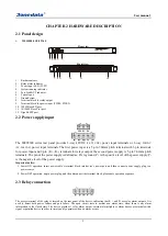
MES5000-4GS-8T16F
Rear view
Front view
1.
Rackmount ears
2.
Relay alarm indicator
3.
Power input LED (P1/P2)
4.
System running indicator
5.
Port Link/ACT indicator
6.
Console port
7.
Ground screw
8.
Terminal block for relay output
9.
Terminal block for power input (PWR1, PWR2)
10.
100M Base-FX port
11.
10/100M Base-T(x) port
12.
Gigabit SFP port
2.2 Power supply input
The MES5000 series rear panel provides 2-way 48VDC
(36~72 VDC)
power input terminals or 2-way
220VAC
(90~264 VAC)
power input terminals. The first power input is a 5-pin 7.62mm pitch terminal with 3-pin terminals
for power input and 2-pin (R +, R-) terminals for relays output; the second power supply is 5-pin 7.62mm pitch
terminals. The pin of the power supply is defined as: FG is ground, P+ is the positive level of the power supply, P-
is the negative level of the power supply.
Important notice:
1.
Power ON operation: insert power cable‘s terminal block into device‘s power port, and then connect power supply plug to a
power source.
2.
Power OFF operation: unpin power plug, and then disconnect the terminal block, please note operation sequence.
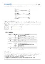
2.3 Relay connection
The access terminal of the relay is located on the rear panel of the device, indicating that R + and R- are relay alarm outputs. It is
used to detect both power failure and port failure. The open circuit state in normal non alarm state, when there is any alarm
information to the closed state. The device provides 1 relay alarm output, external alarm lights or alarm buzzer or external switch
signal acquisition device in order to timely notify operators when an alarm occurs.


