background image

4

1

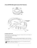
Unpacking the Access Point

Make sure that you have the following items, which are included with the access point:

Mounting Kit:

One universal mounting bracket (attached to the access point)

One paper mounting template (used for marking cutting areas and screw holes)

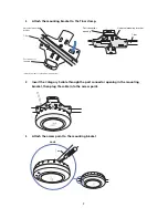
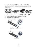
One two-piece 14.2-mm (9/16-inch) T-bar clamp

One two-piece 15.9-mm (5/8-inch) T-bar clamp

One two-piece 23.9-mm (15/16-inch) T-bar clamp

Two #6 sheet metal screws and two drywall anchors

Three adhesive rubber feet (used for a tabletop installation).

2

Preparing for Installation

It is advisable to connect the power (if using an external power supply) and check the Ethernet cables 
and LEDs before installing the access point in a hard-to-reach location. Additionally, observe the 
following before mounting or connecting the access point:

Cabling

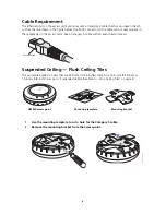
Make sure that standard Category 5 cable with straight-through signaling is 

installed at the site before you install the access point.


Make sure that the cable is highly flexible and that there is no extra covering 
on the RJ-45 connector that could prevent the cable from being routed 
through the mounting bracket

Power

Power must be supplied via an 802.3af Power Over Ethernet (PoE)-compliant 
device. Removal of the Ethernet cable is the only method of disconnecting 
power from the access point.


With the advanced functionality of three 

transmitters and three receivers (3 x 3 MIMO) in this dual radio 802.11a/b/g/n 
Access Point, the AP 3950 power demands exceed the 802.3af power limits.  
The AP 3950 has an auto-sense capability so that, when only 802.3af power 
is supplied, it turns on in a 2 x 3 mode.   When 802.3af+ (also known as pre-
802.3at) or two 802.3af ports are used, the AP 3950 comes up in full 3 x 3 
mode.

WARNING:

  Before using a wireless device in a hazardous location, consult the local codes, national 

codes, and safety directors of the location for usage constraints.

WARNING: 

Do not connect or disconnect cables or otherwise work with the access point 

hardware during periods of lightning activity.

NOTE: 

The access point is intended for indoor use only. Do not install the device outdoors, 

unless you install it in a properly installed enclosure.

NOTE: 

To reduce the possibility of connection interference caused by dust, clean the 

Category 5 connector pins before inserting a cable into the access point.

Содержание 3CRWX395075A - Wireless LAN Managed Access Point...

Страница 1: ...WXR100 Power is supplied via Power Over Ethernet PoE Since the throughput of the AP 3950 is greater than 100Mb s it is recommended that the AP 3950 be connected to a Gigabit Ethernet port The followin...

Страница 2: ...be ordered separately Lock and Unlock Holes On one side of the access point there is a lock hole On the other side there is an unlock hole Insert a 3 mm or 1 8 inch screwdriver into the appropriate ho...

Страница 3: ...ou can use either port to connect the access point to a WX controller However the access point always attempts to boot on port 1 first Only if the boot attempt on port 1 fails does the access point at...

Страница 4: ...revent the cable from being routed through the mounting bracket Power Power must be supplied via an 802 3af Power Over Ethernet PoE compliant device Removal of the Ethernet cable is the only method of...

Страница 5: ...MAC address is printed on the back of the access point Additional MAC address labels are shipped with the access point 3 Mounting the Access Point The access point can be mounted on the following typ...

Страница 6: ...nstead Suspended Ceiling Flush Ceiling Tiles This procedure applies to T bars that are 23 9 mm 15 16 inches wide For a 14 2 mm 9 16 inch or 15 9 mm 5 8 inch T bar go to Suspended Ceiling Installation...

Страница 7: ...unting bracket then plug the cable into the access point 5 Attach the access point to the mounting bracket T bar Viewed from above ceiling tiles looking down 840 9502 0005 Universal mounting bracket P...

Страница 8: ...ut a hole for the Category 5 cable 2 Install the T bar clamp that fits the T bar T bar clamps use set that fits T bar Mounting template Mounting bracket Mobility point TM AP3950 access point Mounting...

Страница 9: ...the port connector opening in the mounting bracket then plug the cable into the access point 840 9502 0011 840 9502 0008 T bar T bar clamps attached to T bar Universal mounting bracket 840 9502 0012...

Страница 10: ...ket Junction Box Installation 1 Remove the mounting bracket from the access point 840 9502 0006 Lock T bar TM TM Mounting hardware Mounting bracket Mobility point TM AP3950 access point Mounting brack...

Страница 11: ...h the bracket to the junction box 3 Plug the Category 5 cable into the access point and attach the access point to the mounting bracket 840 9502 0017 Junction box Port connector opening 840 9502 0062...

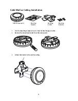
Страница 12: ...y 5 cable 2 Remove the mounting bracket from the access point 3 Attach the bracket to the wall or ceiling Mounting hardware Mounting template Mounting bracket Mobility point TM AP3950 access point Mou...

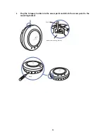
Страница 13: ...13 4 Plug the Category 5 cable into the access point and attach the access point to the mounting bracket 840 9502 0016 Universal mounting bracket Cable TM 840 9502 0062 Lock TM TM...

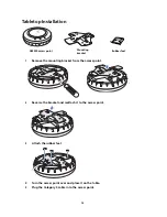
Страница 14: ...ach it to the access point 3 Attach the rubber feet 4 Turn the access point over and place it on the table 5 Plug the Category 5 cable into the access point Rubber feet Mounting bracket Mobility point...

Страница 15: ...port as an AP3950 managed access point and then insert the cable into the controller and verify the link To connect the access point indirectly to a 3Com Wireless LAN Controller through the network c...

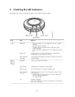
Страница 16: ...ng green and amber The access point is booting and receiving its configuration file from a wireless controller Radio 1 2 4 GHz Radio 2 5 0 GHz Solid green A client is associated with the radio Blinkin...

Страница 17: ...tic fields 0 Hz to 300 GHz US RADIO FREQUENCY REQUIREMENTS This device must not be co located or operated in conjunction with any other antenna or transmitter This device is for indoor use only when u...

Страница 18: ...f est autoris e seulement aux conditions suivantes 1 il ne doit pas produire de brouillage et 2 l utilisateur du dispositif doit tre pr t accepter tout brouillage radio lectrique re u m me si ce broui...

Страница 19: ...ve shod se z kladn mi pozadavky a dal mi p slu n mi ustanoven mi sm rnice 1999 5 ES Dansk Danish Undertegnede 3Com Corporation erkl rer herved at f lgende udstyr RLAN device overholder de v sentlige...

Страница 20: ...k vetelm nyeknek s az 1999 5 EC ir nyelv egy b el r sainak Malti Maltese Hawnhekk 3Com Corporation jiddikjara li dan RLAN device jikkonforma mal htigijiet essenzjali u ma provvedimenti ohrajn relevant...

Страница 21: ...the area The presence of nearby radar operation may result in temporary interruption in communications of this device The Access Point s radar detection feature will automatically restart operation o...

Страница 22: ...s reserved 3Com and the 3Com logo are registered trademarks of 3Com Corporation All other company and product names may be trademarks of the respective companies with which they are associated Part Nu...

Отзывы: