background image

|  8 - STACKING LCC84/LCC44 ON SUB310 USING THE TOWER RIGGING SYSTEM

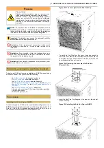
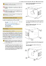
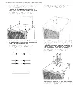
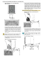
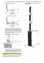
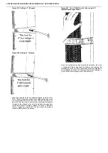
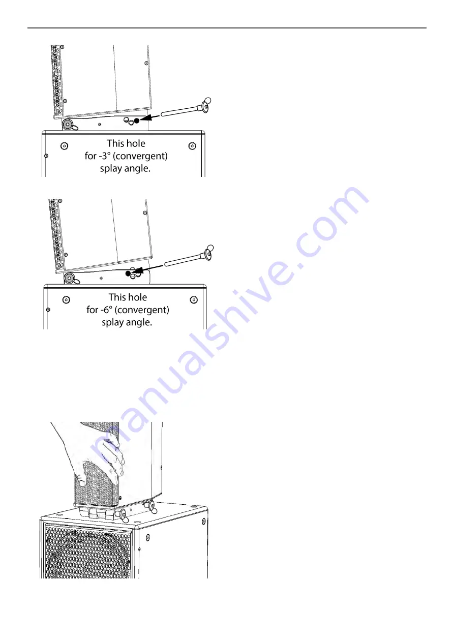
Figure  163. Setting a -3° tilt angle.

Figure  163. Setting a -6° tilt angle.

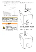
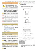
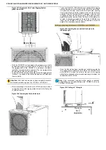
When the required holes are perfectly aligned, take the other 
M10×100 ball-lock pin supplied with the rigging plates and press 
the  lock-release  button  on  the  rear  of  the  pin  to  allow  it  to 
pass into the hole. Insert it into the holes, pushing it completely 
through all four aligned holes until the ball-lock emerges from 
the far side. When it emerges, release the button to allow the 
lock  to  engage  and  assure  that  the  pin  cannot  be  removed 
without again pressing the release.

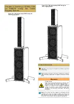
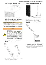
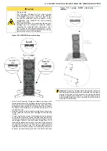
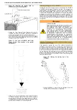
Figure   165.  LCC84  fully  coupled  to  SUB310  (0° 
angle shown).

Once the second pin has been inserted and locked, the array 
is configured. Before releasing the enclosure and allowing the 
assembly to stand on its own, physically assure the stability of 
the installation and that it will not tip with mild force applied in 
any direction at the highest point of the assembly.

Содержание CSUB210

Страница 1: ...1 SOUND INC 34 Apple Street Tinton Falls NJ 07724 1 732 798 9900 www 1 sound com W O R K I N G D R A F T Stacked and Pole Mounted Deployments of the Tower System ...

Страница 2: ...Active Speaker Tube using the Tower Tube Mount 36 Installing the Tower Tube Mount on a Tower Rigging System Plate 37 Installing Rigging Plate on LCC44 84 38 Coupling Tower Tube Mount and LCC44 using the Tower Rigging System 39 Mounting LCC44 on Active Speaker Tube using the Tower Rigging System 40 Chapter 6 Deploying LCC44 on an Active Speaker Tube atop CSUB210 44 Critical information 44 Products ...

Страница 3: ...gging plate on CSUB610 80 Installing Outriggers on the CSUB610 81 Installing Rigging Plate on LCC44 84 85 Coupling LCC44 84 units to CSUB610 using Tower Rigging System 86 Coupling Stacked LCC84 or LCC44 units via the Tower Rigging System 88 ...

Страница 4: ...ious lengths Dimensions 17 8 452 mm x 6 3 160 mm x 9 5 240 mm Colors Stocking black and white custom colors and fabrics available TOWER LCC84 Cardioid Column Line Array Enclosure Figure 2 LCC84 with Tower Rigging System left and without Tower LCC84 is a cardioid line array element featuring designed to be compact high powered and array able The enclosure features Clarity Technology a proprietary h...

Страница 5: ...t is a line source subwoofer capable of operating in cardioid sub cardioid end fire and omnidirectional modes and designed for positioning parallel or perpendicular to walls or even low profile 11 75 high horizontal deployment This bass enclosure offers the sound of a double 18 subwoofer in omni mode CSUB610 is designed to accept proprietary Tower Rigging System plates for stacking multiple LCC44 ...

Страница 6: ...lors Stocking black and white custom colors and fabrics available SUB12 Figure 6 SUB12 The SUB12 is a high powered high performance passive bass reflex subwoofer unit It is equipped with one 12 low frequency driver with a 4 voice coil The bass response extends down to 35 Hz with low distortion The SUB12 has a compact build making it lightweight There are two recessed NL4 connectors so the sub can ...

Страница 7: ... 16 in Speaker Tube The 40 cm 16 Speaker Tube is a simple steel square section speaker pole for mounting satellite speaker enclosures atop subwoofers It is available with a black or white finish The kit includes The Speaker Tube Tower Tube Mount Figure 9 Tower Tube Mount The Tower Tube Mount enables a Tower loudspeaker to be coupled with the proprietary Active Speaker Tubes for deployment of LCC44...

Страница 8: ...num This system is used to attach a Tower loudspeaker to either another Tower column a subwoofer or a fly bar It can also be used with the Tower Tube Mount to allow variable divergent or convergent splay angles The plates are available with an anodized black or silver finish The kit includes 2 Rigging Plates 2 stainless steel M10x100 ball lock pins 8 M6 50 mm stainless steel countersunk socket hea...

Страница 9: ...ch satellite enclosures are mounted on top of the subwoofers The outriggers have screw adjustable feet for leveling the subwoofer Two of the outriggers extend forward at 50 to provide extended stability at the front of the cabinet while the other two are angled at 90 The outriggers are ideal for applications in which the subs are in an environment where people could bump into them or lean on them ...

Страница 10: ...e from walkways trafficked areas and the general public to minimize risk of injury or damage to the enclosures themselves and associated equipment Notice This product must be installed in compliance with all applicable local state and national regulatory provisions The responsibility rests with the installer to verify that the installation is carried out in accordance with any applicable legislati...

Страница 11: ...ated against the base Check to see that there is no movement possible of the Speaker Tube with respect to the base plate Figure 18 The fully Assembled Active Speaker Tube and Base Installing the Tower Tube Mount directly on LCC44 The Tower Tube Mount can be used in two different ways depending on the requirements of the application It can be installed directly to an LCC44 or LCC84 unit when the de...

Страница 12: ... sure that the 3 angle of the bottom of the enclosure is complemented by the 3 angle of the top plate of the Tower Tube Mount returning the long side of the Tube Mount to form a straight line parallel to the vertical axis of the enclosure Figure 21 Aligning Tower Tube Mount on LCC44 top and side view Align the two countersunk holes in the Tower Tube Mount with the threaded inserts in the rigging p...

Страница 13: ...aker enclosure atop any of them DO NOT ATTEMPT TO MOVE OR REPOSITION A SUB SATELLLITE ASSEMBLY OR A FREE STANDING SPEAKER STAND WITH AN ENCLOSURE MOUNTED ATOP IT WARNING Tipping Hazard DO NOT USE THE TOWER RIGGING SYSTEM PLATES TOGETHER WITH THE TOWER TUBE MOUNT AND SPEAKER TUBES FOR SUBWOOFER SATELLITE CONFIGURATIONS ATOP THE SUB12 OR CSUB210 MODELS OR WITH THE ACTIVE SPEAKER TUBE WITH BASE The u...

Страница 14: ... as it enters It should stop firmly when the Tube arrives at the top of the Mount with the bottom of the Tower Tube Mount coming to 2 cm above the top SpeakOn connector Figure 24 LCC44 with Tower Tube Mount installed on Active Speaker Tube Physically assure the stability of the installation and that it will not tip using mild force applied in any direction at the highest point of the assembly ...

Страница 15: ...le legislation Important The installer must assess the appropriate stability and sturdiness of the deployment surface Restriction Only hardware and accessories included with the product or specified by 1 Sound should be used for its installation Restriction Do not modify or alter the loudspeaker or any accessory Any modification by the user or installer could render the product or the installation...

Страница 16: ...subwoofer in an upright position The CSUB610 unit can be deployed with LCC44 LCC84 or combinations of these in either a parallel or perpendicular configuration Each of these configurations requires that the outriggers be installed in the appropriate configuration WARNING TIPPING HAZARD Speaker enclosures stacked atop one another even when properly coupled represent a tipping hazard TO REDUCE THE R...

Страница 17: ...lel deployment of LCC44 84 units bottom view Using a 5 mm hex wrench remove the two bottom rigging point screws from one long side of the CSUB610 cabinet Figure 32 Aligning forward Outrigger on CSUB610 bottom view Align the mounting hole of the longer 50 Outrigger with the bottom rigging point nearest the front grille of the subwoofer and thread in the M8 screw into the threaded insert of the rigg...

Страница 18: ...s firmly around the rubber foot of the subwoofer and flush with the bottom surface of the subwoofer cabinet Figure 35 Aligning rear Outrigger on CSUB610 side view Using a 5 mm hex wrench fully tighten the countersunk M8 screw into the rigging point Repeat steps the steps above on the opposite side of the CSUB610 Figure 36 Lowering the Outrigger feet Turn the leveling feet of each outrigger to lowe...

Страница 19: ...id placing it on non flush elements such as the Sub Pole Cup Read the level and if the Subwoofer is slightly out of level side to side adjust the feet of the pair of Outriggers on the side that is lower To raise the side that is lower the Outrigger feet can be lowered by turning them clockwise as seen from the top of the cabinet It may be necessary to tilt the entire subwoofer slightly to raise th...

Страница 20: ...facing the rear of the subwoofer cabinet and assure that it is firmly seated in the Pole Cup For special applications in order to meet the requirements of the audience s listening height the 40 cm Speaker Tube can be used in the place of the 95 cm model in this configuration WARNING TIPPING HAZARD DO NOT USE THE 145 cm ACTIVE SPEAKER TUBE TO MOUNT AN LCC44 UNIT ATOP THE CSUB610 OR SUB310 SUBWOOFER...

Страница 21: ...two M6 16 mm screws from the rigging points indicated above on the bottom side of the cabinet Put these aside as they will be used to mount the Tower Tube Mount Position the Tower Tube Mount upside down with the open side up and the countersunk drilled plate against the bottom of the enclosure making sure that the 3 angle of the bottom of the enclosure is complemented by the 3 angle of the top pla...

Страница 22: ... speaker enclosure atop any of them DO NOT ATTEMPT TO MOVE OR REPOSITION A SUB SATELLLITE ASSEMBLY OR A FREE STANDING SPEAKER STAND WITH AN ENCLOSURE MOUNTED ATOP IT WARNING Tipping Hazard DO NOT USE THE TOWER RIGGING SYSTEM PLATES TOGETHER WITH THE TOWER TUBE MOUNT AND SPEAKER TUBES FOR SUBWOOFER SATELLITE CONFIGURATIONS ATOP THE SUB12 OR CSUB210 MODELS OR WITH THE ACTIVE SPEAKER TUBE WITH BASE T...

Страница 23: ...losure to be tilted 3 0 or 3 with respect to the floor and another that allows only downward angles of 3 6 and 9 To attach the Tower Tube Mount to a Tower Rigging System rigging plate Lay the Tower Rigging System plate flat with the uniform surface up Figure 48 Mounting holes for Tower Tube Mount on the Tower Rigging System plate Position the Tower Tube Mount upside down with the open side up and ...

Страница 24: ... ground stacked or pole mounted deployments Figure 52 Threaded inserts for Rigging Plate on the bottom of LCC44 or LCC84 Invert the LCC44 84 enclosure bottom side up Figure 53 Removing the screws from the LCC44 84 Rigging System mounting points Use a 4 mm Allen wrench or hex driver to remove the six M6 16 mm screws from the rigging points indicated above on the bottom side of the cabinet Put these...

Страница 25: ... the tilt angle already set atop the Active Speaker Tube Position the LCC44 with a rigging plate installed on the bottom upside down Rigging Plate side up on a floor or table Invert the Tube Mount Rigging Plate assembly Tube Mount up and interlock the forward sections of the two rigging plates in a manner that the Tower Tube Mount is laterally centered over the enclosure the two plates will not fu...

Страница 26: ... the Active Speaker Tube with Base or improper installation of the Active Speaker Tube Sub Pole Cup or Subwoofer Outriggers on a subwoofer enclosure or of the Tower Tube Mount on the LCC44 could create a hazardous or unstable condition when the LCC44 is mounted atop them Follow all specific instructions for the assembly of each of these products and verify their stable and level condition before a...

Страница 27: ...direction at the highest point of the assembly Adjusting tilt Though it is preferable to set the tilt angle of the enclosure before mounting the LCC44 atop the Active Speaker Tube it is possible to adjust the tilt angle of the enclosure using the Tower rigging System when it is already mounted on the Speaker Tube WARNING TIPPING HAZARD Two People Required When adjusting the tilt angle of an LCC44 ...

Страница 28: ... tilt of the enclosure to align the set of holes in the two rigging plates that correspond to the desired angle Re insert the ball lock pin into the appropriate holes pushing it completely through all four aligned holes until the ball lock emerges from the far side When it emerges allow the lock to engage and assure that the pin cannot be removed without again pressing the release Figure 62 Adjust...

Страница 29: ...r installer could render the product or the installation unsafe Restriction Do not install a loudspeaker or any accessory near any open flame or heat source Products accessories and tools required To deploy an LCC44 enclosure as a satellite on a SUB310 bass unit using an Active Speaker Tube you will need the following An LCC44 on page 4 loudspeaker enclosure A SUB310 on page 5 subwoofer enclosure ...

Страница 30: ... Cup To begin this procedure while the SUB310 is still upright rigging plate side up use a 5 mm hex wrench to remove the four countersunk M8 25 mm screws from the rigging points in the four corners of top side of the cabinet Keep these screws Lay the SUB310 on one of the long sides taking whatever necessary precautions to avoid damaging the finish of the cabinet or the grill Both of the smaller 40...

Страница 31: ...ling Outriggers on the SUB310 Installing the subwoofer outriggers improves the stability of the CSUB610 or SUB310 when deployed vertically on the floor The outriggers are recommended in any application in which the subs are deployed in public areas where people could bump into them or lean on them These are also REQUIRED in any application in which other loudspeaker enclosures are coupled to the s...

Страница 32: ...ing sure that the bottom bracket of the Outrigger fits firmly around the rubber foot of the subwoofer and flush with the bottom surface of the subwoofer cabinet Figure 76 Aligning forward Outrigger on SUB310 side view Using a 5 mm hex wrench fully tighten the countersunk M8 screw into the rigging point Figure 77 Aligning rear Outrigger on SUB310 bottom view Align the mounting hole of the shorter 9...

Страница 33: ...loor stage deck riser etc in order to level it before deployment It is the responsibility of the installation personnel to verify and guarantee the safety of the installation Figure 80 SUB310 Side to side leveling With all four Subwoofer Outriggers installed and each of the four adjustable feet of the Outriggers lowered to touch the floor place a spirit level or digital level across the top surfac...

Страница 34: ...imes to achieve correct leveling Once the subwoofer unit has been leveled both side to side and front to back check again the leveling on both axes making any slight adjustments necessary until the cabinet is level both side to side and front to back Installing Active Speaker Tube on SUB310 In order to deploy an LCC44 unit in a sub satellite configuration atop a CSUB610 or SUB310 unit with the Sub...

Страница 35: ...can be obtained with the directivity axis of the enclosure parallel 0 to the floor Otherwise when the application requires that the LCC44 84 unit be adjustable in tilt with respect to the floor the Tower Tube Mount can be attached to a Tower Rigging System rigging plate to allow different tilt angles To install the Tower Tube Mount directly to an LCC44 enclosure Figure 85 Threaded inserts for Towe...

Страница 36: ...ther atop a subwoofer in a sub satellite configuration or independently atop an Active Speaker Tube with base WARNING Tipping Hazard Improper assembly of the Active Speaker Tube with Base or improper installation of the Active Speaker Tube Sub Pole Cup or Subwoofer Outriggers on a subwoofer enclosure or of the Tower Tube Mount on the LCC44 could create a hazardous or unstable condition when the LC...

Страница 37: ...stallation and that it will not tip using mild force applied in any direction at the highest point of the assembly Installing the Tower Tube Mount on a Tower Rigging System Plate When the application requires that the LCC44 84 unit be adjustable in tilt with respect to the floor the Tower Tube Mount can be attached to a Tower Rigging System rigging plate to allow different tilt angles There are tw...

Страница 38: ...ry firmly Installing Rigging Plate on LCC44 84 In order to couple LCC44 or LCC84 units to each other directly to a subwoofer or to allow for variable tilt angles of the enclosure in sub satellite configurations using the Tower Tube mount and Active Speaker Tube the speaker enclosure needs to be equipped with Tower Rigging System plates If the LCC44 or LCC84 unit is not pre equipped with Rigging Pl...

Страница 39: ...e no movement possible If the LCC44 or LCC84 unit is being deployed as a single unit in a sub satellite configuration atop a subwoofer using a Tower Tube Mount equipped with a rigging plate or as a single unit with no further enclosures above it directly atop a subwoofer equipped with a rigging plate it is not necessary to mount the second rigging plate on the top of the enclosure If instead the L...

Страница 40: ...he tower tube mount installed so as to align the rear holes of the two plates that correspond to the desired tilt angle Figure 99 Setting tilt angle with the Tower Tube Mount configured for 3 0 and 3 Figure 100 Setting tilt angle with the Tower Tube Mount configured for 3 6 and 9 Figure 101 Fixing tilt angle of Tower Rigging System and Tower Tube Mount 3 shown When the required holes are perfectly...

Страница 41: ...BE WITH BASE The use of pole mounted configurations of the LCC44 model enclosure with the inclinable Tower Rigging System plates is possible only atop the CSUB610 or SUB310 model subwoofers Make sure that the 95 cm Active Speaker Tube is properly installed in the CSUB610 or SUB310 either model equipped with Outriggers and properly leveled and positioned for use or that the free standing 175 cm Act...

Страница 42: ...sult from possible toppling of loudspeaker enclosures DO NOT attempt this adjustment alone One person should maintain control of the LCC44 at all times while a second operator should carry out the tilt adjustment WARNING Risk of Hand Injury When adjusting the tilt angle of an LCC44 or the splay angle between two units do not allow your fingers to enter the space between the two rigging plates or a...

Страница 43: ...nfiguration Figure 106 Adjusting tilt of LCC44 on Tower Tube Mount in 3 6 9 configuration Before releasing the enclosure and allowing the assembly to stand on its own physically assure the stability of the installation and that it will not tip with mild force applied in any direction at the highest point of the assembly ...

Страница 44: ... enclosures on floor stands WARNING Tipping Hazard Speaker enclosures stacked atop one another even when properly coupled represent a tipping hazard Exercise extreme care when assembling speaker arrays as a stack of them toppling or collapsing creates a risk of serious injury or death as well as likely damage to the enclosures themselves and nearby equipment Notice This product must be installed i...

Страница 45: ...n page 7 or the 40 cm Passive Speaker Tube on page 7 The Tower Tube Mount on page 7 adapter kit A 4 mm hex driver at least 10 cm long preferably magnetized A 4 mm Allen wrench Threadlocking compound Procedures Installing Sub Pole Cup on CSUB210 In order to deploy an LCC44 unit in a sub satellite configuration atop a CSUB210 subwoofer unit the subwoofer must first be equipped with a Sub Pole Cup If...

Страница 46: ...OSSIBLE TOPPLING OF LOUDSPEAKER ENCLOSURES ONLY THE 95 cm ACTIVE SPEAKER TUBE TO MOUNT ENCLOSURES IN SUB SATELLITE CONFIGURATIONS ATOP THE CSUB610 OR SUB310 SUBWOOFER MODELS Figure 113 Installing the 145 cm Active Speaker Tube on the CSUB210 Align the Active Speaker Tube with the Sub Pole Cup installed in the subwoofer with the SpeakOn connectors oriented toward the rear of the subwoofer cabinet w...

Страница 47: ...ition the Tower Tube Mount upside down with the open side up and the countersunk drilled plate against the bottom of the enclosure making sure that the 3 angle of the bottom of the enclosure is complemented by the 3 angle of the top plate of the Tower Tube Mount returning the long side of the Tube Mount to form a straight line parallel to the vertical axis of the enclosure Figure 117 Aligning Towe...

Страница 48: ... speaker enclosure atop any of them DO NOT ATTEMPT TO MOVE OR REPOSITION A SUB SATELLLITE ASSEMBLY OR A FREE STANDING SPEAKER STAND WITH AN ENCLOSURE MOUNTED ATOP IT WARNING Tipping Hazard DO NOT USE THE TOWER RIGGING SYSTEM PLATES TOGETHER WITH THE TOWER TUBE MOUNT AND SPEAKER TUBES FOR SUBWOOFER SATELLITE CONFIGURATIONS ATOP THE SUB12 OR CSUB210 MODELS OR WITH THE ACTIVE SPEAKER TUBE WITH BASE T...

Страница 49: ... as it enters It should stop firmly when the Tube arrives at the top of the Mount with the bottom of the Tower Tube Mount coming to 2 cm above the top SpeakOn connector Figure 120 LCC44 with Tower Tube Mount installed on Active Speaker Tube Physically assure the stability of the installation and that it will not tip using mild force applied in any direction at the highest point of the assembly ...

Страница 50: ... Tube atop SUB12 Figure 122 LCC44 deployed on the 95 cm Active Speaker Tube atop SUB12 Critical information Attention This equipment is intended for installation by qualified professionals Notice Please read these instructions carefully and completely before attempting deployment of speaker enclosures on floor stands ...

Страница 51: ... source Products accessories and tools required To deploy an LCC44 enclosure as a satellite on a SUB12 bass unit using an Active Speaker Tube you will need the following An LCC44 on page 4 loudspeaker enclosure A SUB12 on page 6 subwoofer enclosure The Sub Pole Cup on page 8 adapter flange kit The 145 cm Active Speaker Tube on page 7 the 95 cm Active Speaker Tube on page 7 or the 40 cm Passive Spe...

Страница 52: ... special applications in order to meet the requirements of the audience s listening height the 95 cm Active Speaker tube or the 40 cm Speaker Tube can be used in the place of the 145 cm model in this configuration WARNING TIPPING HAZARD DO NOT USE THE 145 cm ACTIVE SPEAKER TUBE TO MOUNT AN LCC44 UNIT ATOP THE CSUB610 OR SUB310 SUBWOOFER TO REDUCE THE RISK OF INJURY OR DAMAGE THAT COULD RESULT FROM...

Страница 53: ... directly to an LCC44 enclosure Figure 129 Threaded inserts for Tower Tube Mount on the bottom of LCC44 or LCC84 Figure 130 Removing screws from Tower Tube Mount attachment points Invert the LCC44 enclosure and use a 4 mm Allen wrench or hex driver to remove the two M6 16 mm screws from the rigging points indicated above on the bottom side of the cabinet Put these aside as they will be used to mou...

Страница 54: ... specific instructions for the assembly of each of these products and verify their stable and level condition before attempting to mount a speaker enclosure atop any of them DO NOT ATTEMPT TO MOVE OR REPOSITION A SUB SATELLLITE ASSEMBLY OR A FREE STANDING SPEAKER STAND WITH AN ENCLOSURE MOUNTED ATOP IT WARNING Tipping Hazard DO NOT USE THE TOWER RIGGING SYSTEM PLATES TOGETHER WITH THE TOWER TUBE M...

Страница 55: ...ing sure that it does not catch or bind as it enters It should stop firmly when the Tube arrives at the top of the Mount with the bottom of the Tower Tube Mount coming to 2 cm above the top SpeakOn connector Figure 134 LCC44 with Tower Tube Mount installed on Active Speaker Tube Physically assure the stability of the installation and that it will not tip using mild force applied in any direction a...

Страница 56: ... enclosures on floor stands WARNING Tipping Hazard Speaker enclosures stacked atop one another even when properly coupled represent a tipping hazard Exercise extreme care when assembling speaker arrays as a stack of them toppling or collapsing creates a risk of serious injury or death as well as likely damage to the enclosures themselves and nearby equipment Notice This product must be installed i...

Страница 57: ...igging plate and configured with the rubber feet on the opposite side from this you can proceed to the installation of the outriggers on page 31 If instead the SUB310 is configured to be deployed with the Sub Pole Cup side up it will first be necessary to mount the rubber feet on the opposite side of the cabinet Important For permanent or semi permanent installation of the Tower Rigging System pla...

Страница 58: ...ghten these Figure 141 The threaded inserts for mounting the Tower Rigging System plate on SUB310 Figure 142 Removing the screws from the inserts for mounting the Tower Rigging System plate Use a 4 mm Allen wrench or hex driver to remove the six M6 50 mm screws from the rigging points indicated above on the top of the cabinet Keep these screws as they will be used to fix the rigging plate Position...

Страница 59: ...pping hazard TO REDUCE THE RISK OF INJURY OR DAMAGE THAT COULD RESULT FROM POSSIBLE TOPPLING OF LOUDSPEAKER ENCLOSURES THE INSTALLATION OF THE SUBWOOFER OUTRIGGERS ON THE SUB310 AND CSUB610 IS REQUIRED WHENEVER ONE OR MORE LOUDSPEAKER ENCLOSURES IS MOUNTED ATOP ONE OF THESE UNITS EITHER IN A STACKED CONFIGURATION USING THE TOWER RIGGING SYSTEM OR IN A SUB SATELLITE CONFIGURATION USING A SPEAKER PO...

Страница 60: ...er fits firmly around the rubber foot of the subwoofer and flush with the bottom surface of the subwoofer cabinet Figure 150 Aligning rear Outrigger on SUB310 side view Using a 5 mm hex wrench fully tighten the countersunk M8 screw into the rigging point Repeat steps 2 6 on the opposite side of the SUB310 Figure 151 Lowering the Outrigger feet Turn the leveling feet of each outrigger to lower it j...

Страница 61: ...avoid placing it on non flush elements such as the Sub Pole Cup Read the level and if the Subwoofer is slightly out of level side to side adjust the feet of the pair of Outriggers on the side that is lower To raise the side that is lower the Outrigger feet can be lowered by turning them clockwise as seen from the top of the cabinet It may be necessary to tilt the entire subwoofer slightly to raise...

Страница 62: ...84 enclosure the use of medium strength threadlocking compound is REQUIRED on all user installed screws WARNING NOT FOR SUSPENDED LOADS For flown deployments of the LCC44 or LCC84 enclosures use only units with factory installed rigging plates LCC44 or LCC84 units with user installed rigging plates are only suitable for ground stacked or pole mounted deployments Figure 155 Threaded inserts for Rig...

Страница 63: ...late has been properly installed it can be coupled in stacked configuration with a single unit of LCC84 or a single LCC44 likewise equipped with a rigging plate WARNING Tipping Hazard Improper installation of the Subwoofer Outriggers or the Tower Rigging System plate on a subwoofer enclosure or of the rigging plate on the LCC44 or LCC84 unit could create a hazardous or unstable condition when the ...

Страница 64: ...100 ball lock pins supplied with the rigging plates and press the lock release on the rear of the pin to allow it to pass into the hole Insert it into the front holes pushing it completely through all four aligned holes until the ball lock emerges from the far side When it emerges allow the lock to engage and assure that the pin cannot be removed without again pressing the release When the fronts ...

Страница 65: ...etely through all four aligned holes until the ball lock emerges from the far side When it emerges release the button to allow the lock to engage and assure that the pin cannot be removed without again pressing the release Figure 165 LCC84 fully coupled to SUB310 0 angle shown Once the second pin has been inserted and locked the array is configured Before releasing the enclosure and allowing the a...

Страница 66: ...e parallel cardioid sub configuration Figure 167 One LCC44 and one LCC84 deployed atop CSUB610 using the Tower Rigging System in the parallel cardioid sub configuration Critical information Attention This equipment is intended for installation by qualified professionals Notice Please read these instructions carefully and completely before attempting deployment of speaker enclosures on floor stands...

Страница 67: ...tabilizing leg kit The Tower Rigging System Plates on page 8 kit A 5 mm Allen wrench A 4 mm Allen wrench Recommended Spirit level Procedures Mounting Rigging plate on CSUB610 In order to use the Tower Rigging System to deploy LCC44 or LCC84 units directly atop a CSUB610 bass unit the subwoofer unit must first be equipped with a Tower Rigging System plate The Tower Rigging System Plate can be mount...

Страница 68: ... with LCC44 LCC84 or combinations of these in either a parallel or perpendicular configuration Each of these configurations requires that the outriggers be installed in the appropriate configuration WARNING TIPPING HAZARD Speaker enclosures stacked atop one another even when properly coupled represent a tipping hazard TO REDUCE THE RISK OF INJURY OR DAMAGE THAT COULD RESULT FROM POSSIBLE TOPPLING ...

Страница 69: ...f the CSUB610 cabinet Figure 175 Aligning forward Outrigger on CSUB610 bottom view Align the mounting hole of the longer 50 Outrigger with the bottom rigging point nearest the front grille of the subwoofer and thread in the M8 screw into the threaded insert of the rigging point making sure that the bottom bracket of the Outrigger fits firmly around the rubber foot of the subwoofer and flush with t...

Страница 70: ...ling feet of each outrigger to lower it just to rest firmly against the floor Leveling CSUB610 Once the Subwoofer Outriggers are securely installed it is possible to use them for fine adjustments to assure that the subwoofer unit is properly leveled which is especially important when other speaker enclosures are to be deployed atop the subwoofer CAUTION Tipping Hazard The Subwoofer Outriggers can ...

Страница 71: ...rning them clockwise as seen from the top of the cabinet It may be necessary to tilt the entire subwoofer slightly to raise the outrigger feet off of the floor before turning them Try to make similar adjustments to each of the pair of feet returning the subwoofer to rest on the floor after each adjustment and checking the level each time This process may need to be repeated several times to achiev...

Страница 72: ...C84 enclosure the use of medium strength threadlocking compound is REQUIRED on all user installed screws WARNING NOT FOR SUSPENDED LOADS For flown deployments of the LCC44 or LCC84 enclosures use only units with factory installed rigging plates LCC44 or LCC84 units with user installed rigging plates are only suitable for ground stacked or pole mounted deployments Figure 183 Threaded inserts for Ri...

Страница 73: ...d with outriggers leveled and a Tower Rigging System plate has been properly installed it can be coupled in stacked configuration with LCC84 or LCC44 units likewise equipped with rigging plates WARNING Tipping Hazard Improper installation of the Subwoofer Outriggers or the Tower Rigging System plate on a subwoofer enclosure or of the rigging plate on the LCC44 or LCC84 unit could create a hazardou...

Страница 74: ... the rigging plates and press the lock release on the rear of the pin to allow it to pass into the hole Insert it into the front holes pushing it completely through all four aligned holes until the ball lock emerges from the far side When it emerges allow the lock to engage and assure that the pin cannot be removed without again pressing the release When the fronts of the plates are coupled it sho...

Страница 75: ...re that the pin cannot be removed without again pressing the release Figure 193 LCC84 44 fully coupled to CSUB610 in the 0 configuration Once the second pin has been inserted and locked the array is configured Before releasing the enclosure and allowing the assembly to stand on its own physically assure the stability of the installation and that it will not tip with mild force applied in any direc...

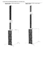
Страница 76: ...STACKED AND POLE MOUNTED DEPLOYMENTS OF THE TOWER SYSTEM Figure 195 Adding an LCC84 to a stacked array of CSUB610 LCC44 Figure 196 Adding an LCC44 to a stacked array of CSUB610 LCC84 ...

Страница 77: ...d press the lock release on the rear of the pin to allow it to pass into the hole Insert it into the front holes pushing it completely through all four aligned holes until the ball lock emerges from the far side When it emerges allow the lock to engage and assure that the pin cannot be removed without again pressing the release When the fronts of the plates are coupled it should be possible to fre...

Страница 78: ... all four aligned holes until the ball lock emerges from the far side When it emerges release the button to allow the lock to engage and assure that the pin cannot be removed without again pressing the release Figure 203 Two LCC84 44 units fully coupled 0 parallel splay angle shown Once the second pin has been inserted and locked the array is configured Before releasing the enclosure and allowing ...

Страница 79: ...dicular omnidirectional sub configuration Figure 205 Three LCC44 enclosures deployed atop CSUB610 using the Tower Rigging System in the perpendicular omnidirectional sub configuration Critical information Attention This equipment is intended for installation by qualified professionals Notice Please read these instructions carefully and completely before attempting deployment of speaker enclosures ...

Страница 80: ...evel Procedures Mounting Rigging plate on CSUB610 In order to use the Tower Rigging System to deploy LCC44 or LCC84 units directly atop a CSUB610 bass unit the subwoofer unit must first be equipped with a Tower Rigging System plate The Tower Rigging System Plate can be mounted in one of two different configurations on a CSUB610 unit either parallel of perpendicular to the front rear axis of the ca...

Страница 81: ...QUIRED in any application in which other loudspeaker enclosures are coupled to the subwoofer in an upright position The CSUB610 unit can be deployed with LCC44 LCC84 or combinations of these in either a parallel or perpendicular configuration Each of these configurations requires that the outriggers be installed in the appropriate configuration WARNING TIPPING HAZARD Speaker enclosures stacked ato...

Страница 82: ...acket of the Outrigger fits firmly around the rubber foot of the subwoofer and flush with the bottom surface of the subwoofer cabinet Figure 213 Installing the first forward Outrigger on CSUB610 front view Using a 5 mm hex wrench fully tighten the countersunk M8 screw into the rigging point Figure 214 Installing the second forward Outrigger on CSUB610 front view Repeat this procedure with the seco...

Страница 83: ...bwoofer Figure 218 Lowering the Outrigger feet Turn the leveling feet of each outrigger to lower it just to rest firmly against the floor Leveling CSUB610 Once the Subwoofer Outriggers are securely installed it is possible to use them for fine adjustments to assure that the subwoofer unit is properly leveled which is especially important when other speaker enclosures are to be deployed atop the su...

Страница 84: ...the top of the cabinet It may be necessary to tilt the entire subwoofer slightly to raise the outrigger feet off of the floor before turning them Try to make similar adjustments to each of the pair of feet returning the subwoofer to rest on the floor after each adjustment and checking the level each time This process may need to be repeated several times to achieve correct leveling When this is ac...

Страница 85: ...Plates on the LCC44 or LCC84 enclosure the use of medium strength threadlocking compound is REQUIRED on all user installed screws WARNING NOT FOR SUSPENDED LOADS For flown deployments of the LCC44 or LCC84 enclosures use only units with factory installed rigging plates LCC44 or LCC84 units with user installed rigging plates are only suitable for ground stacked or pole mounted deployments Figure 22...

Страница 86: ... or the Tower Rigging System plate on a subwoofer enclosure or of the rigging plate on the LCC44 or LCC84 unit could create a hazardous or unstable condition when the subwoofer and column enclosure are assembled Follow all specific instructions for the assembly of each of these products and verify their stable and level condition before attempting to mount a speaker enclosure atop any of them DO N...

Страница 87: ...possible to fix the tilt angle of the coupled speaker enclosure Setting splay angle between LCC84 44 and CSUB610 Figure 228 Inserting the second ball lock pin to fix the splay angle Once the first pin has been inserted and locked to couple the two rigging plates maintain a firm hold on the LCC84 LCC44 unit and tilt it to align the holes in the rear of the rigging plates that correspond to the requ...

Страница 88: ...ically assure the stability of the installation and that it will not tip with mild force applied in any direction at the highest point of the assembly Coupling Stacked LCC84 or LCC44 units via the Tower Rigging System It is possible to create stacked arrays with up to three LCC44 enclosures or one LCC84 plus one LCC44 enclosure atop a CSUB610 subwoofer unit that has equipped with outriggers and pr...

Страница 89: ...CC44 84 UNITS ON CSUB610 IN THE PERPENDICULAR CONFIGURATION USING THE TOWER RIGGING SYSTEM Figure 234 Adding an LCC84 to a stacked array of CSUB610 LCC44 Figure 235 Adding an LCC44 to a stacked array of CSUB610 LCC84 ...

Страница 90: ...ase on the rear of the pin to allow it to pass into the hole Insert it into the front holes pushing it completely through all four aligned holes until the ball lock emerges from the far side When it emerges allow the lock to engage and assure that the pin cannot be removed without again pressing the release When the fronts of the plates are coupled it should be possible to freely tilt the top LCC8...

Страница 91: ...ng it completely through all four aligned holes until the ball lock emerges from the far side When it emerges release the button to allow the lock to engage and assure that the pin cannot be removed without again pressing the release Figure 242 Two LCC84 44 units fully coupled 0 parallel splay angle shown Once the second pin has been inserted and locked the array is configured Before releasing the...

Страница 92: ...Jersey 07724 U S A tel 1 732 798 9900 www 1 sound com sales 1 sound com 2022 1 SOUND All rights reserved No part of this publication may be reproduced or transmitted in any form or by any means without the express written consent of the publisher ...

Отзывы: