STACKED AND POLE-MOUNTED DEPLOYMENTS OF THE TOWER SYSTEM
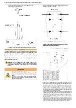
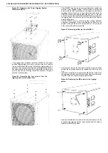
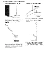
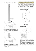
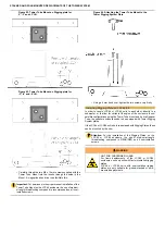
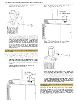
Figure 92. Tower Tube Mount on Rigging plate for
0°, -3° and +3° tilt.
Figure 93. Tower Tube Mount on Rigging plate for
-3°, -6° and -9° tilt.
•
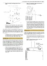
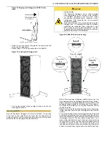
Carefully thread the two M6 x 12 mm screws supplied with the
Tower Tube Mount into the inserts through the holes in the
Mount. A magnetized hex driver can facilitate this.
Important: For permanent or semi-permanent installation of the
Tower Tube Mount on the LCC44 enclosure, the use of medium-
strength threadlocking compound is recommended on all user-
installed screws.
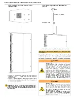
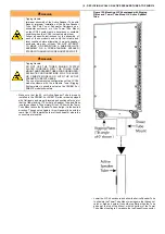
Figure 94. Attaching the Tower Tube Mount to the
Tower Rigging System Plate
•
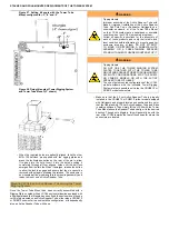
Using a 4 mm hex driver, tighten the two screws very firmly.
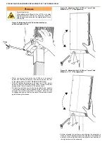
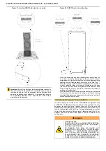
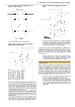
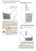
Installing Rigging Plate on LCC44/84
In order to couple LCC44 or LCC84 units to each other, directly to a
subwoofer, or to allow for variable tilt angles of the enclosure in sub/
satellite configurations using the Tower Tube mount and Active Speaker
Tube, the speaker enclosure needs to be equipped with Tower Rigging
System plates.
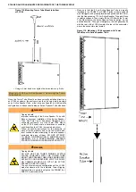
If the LCC44 or LCC84 unit is not pre-equipped with Rigging Plates, these
can be mounted by the user.
Attention: For the installation of the Rigging Plates on the
LCC44 or LCC84 enclosure, the use of medium-strength
threadlocking compound is REQUIRED on all user-installed
screws.
WARNING
NOT FOR SUSPENDED LOADS
For flown deployments of the LCC44 or LCC84
enclosures, use only units with factory-installed rigging
plates.
LCC44 or LCC84 units with user-installed rigging
plates are only suitable for ground-stacked or pole-
mounted deployments.

