STACKED AND POLE-MOUNTED DEPLOYMENTS OF THE TOWER SYSTEM
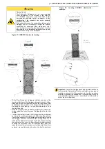
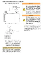
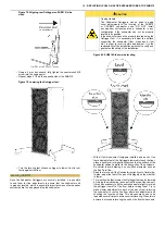
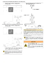
Figure 65. Removing the Tower Rigging System
Plate from SUB310.
•
If the rigging plate is installed, stand the SUB310 in the upright
position (rigging plate up) use a 4 mm hex wrench to remove
the six countersunk M6 screws that hold the rigging plate. The
plate can then be simply removed and put aside, along with the
M6 screws that held it in place. If the original M6×16 mm screws
used to cap the six mounting inserts are available, it is good
practice to replace them.
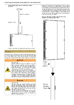
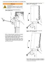
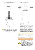
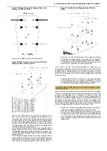
Figure 66. Removing the four screws from the
rigging points for the rubber feet.
•
If the SUB310 has been previously configured for upright use
with the Tower Rigging System, it will still need to be inverted
and the rubber feet re-installed on the opposite end before
installing the Sub Pole Cup. To begin this procedure, while the
SUB310 is still upright (rigging plate side up), use a 5 mm hex
wrench to remove the four countersunk M8×25 mm screws from
the rigging points in the four corners of top side of the cabinet.
Keep these screws.
•
Lay the SUB310 on one of the long sides, taking whatever
necessary precautions to avoid damaging the finish of the
cabinet or the grill. Both of the smaller (40 cm × 30 cm) faces
of the cabinet should be accessible.
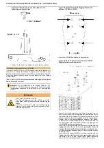
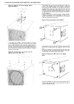
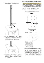
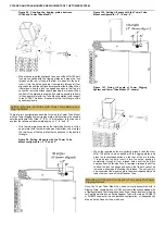
Figure 67. Removing rubber feet from SUB310.
•
Unscrew and remove the four rubber feet from the end of the
cabinet that is predisposed for the installation of the Sub Pole
Cup.
•
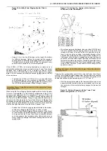
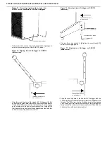
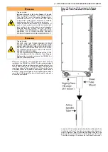
Insert and thread the four countersunk M8×25 mm screws into
the rigging points from which the four rubber feet were removed.
Use the 5 mm hex wrench to lightly tighten these.
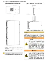
Figure 68. Replacing the M8 screws in the rigging
points.
•
Insert and thread the four rubber feet removed above into the
corresponding rigging points on the opposite end of the cabinet.
Tighten these firmly by hand.


