


MultiScanner
®
x85
OneStep
®
Multifunction Scanner
Visit www.ZirconEurope.com for the most current instructions.
EN
1. INSTALLING THE BATTERIES
This tool requires three new AAA (LR03) batteries.
To install or replace the batteries, locate the battery door on the lower backside of the tool.
Press battery door tab in and lift up. Remove old batteries, if needed, and insert three new AAA
batteries, matching the positive (+) and negative (-) terminals according to diagram on tool.
Lower battery door and snap shut.
Upon insertion of batteries, the tool will automatically power on. The blue backlit LCD screen will
illuminate and the MODE icon will power up. The Battery Strength Indicator will appear and the
Signal Strength Indicator bars slowly ramp down during the calibration process. The SpotLite
®
Pointer
will flash and the unit will beep once to indicate the calibration process is complete.
Low Battery Indication:
The Battery Strength Indicator icon displays the battery level. When the
battery icon drops down to one bar, the battery level is too low for proper operation of the
MultiScanner
®
x
85. Please replace all three AAA batteries as the tool will not operate correctly
when the battery level is too low. When the battery icon begins to flash, the battery level is not
sufficient to power the tool and the tool’s findings should not be considered accurate. Please replace
all three batteries with a new set immediately.
Battery Saving Mode:
Tool will automatically shut off after 3 minutes of non-use.
To manually power off the tool, press and hold the MODE button for approximately 2 seconds.
2. OPERATING TIPS
For optimum scanning results, it is important to properly hold the MultiScanner
®
x
85 and move
slowly when scanning in STUD SCAN, DEEPSCAN_
®
, and AC modes, and scan briskly in Thermal
mode. The following tips will provide more accurate scanning results:
• Grasp the handle with your thumb on one side and your fingers on the other side. Make sure
your fingertips are not touching the surface being scanned or the scanning head of the tool.
• Keep a firm and steady grip on the tool and allow it to calibrate. Moving finger
placement will affect the calibration. Press the MODE button once to recalibrate,
if necessary.
• Hold the tool straight up and down, parallel to the studs, and do not rotate the tool.
• Keep tool flat against the surface and do not rock, tilt, or press hard when slowly sliding
across the surface being scanned.
• Avoid placing your other hand, or any other part of your body, on the surface being scanned.
This will interfere with the tool’s performance.
If you’re receiving erratic scanning results, it may be a result of humidity, moisture within the wall cavity or
drywall, or recently applied paint or wallpaper that hasn’t fully dried. While the moisture may not always be
pvisible, it will interfere with the tool’s sensors. Please allow a few days for the wall to dry out.
WORKING WITH DIFFERENT MATERIALS
Wallpaper:
MultiScanner
®
x
85 functions normally on walls covered with wallpaper or fabric, unless the materials
are metallic foil, contain metallic fibers, or are still wet after application.
Wallpaper may need to dry for several
weeks after application.
Freshly painted walls:
May take one week or longer to dry after application.
Lath & plaster:
Due to irregularities in plaster thickness, it may be difficult for MultiScanner
®
x
85 to locate studs
in STUD SCAN or DEEPSCAN
®
mode. If the plaster has metal mesh reinforcement, MultiScanner
®
x
85 will not be
able to detect through that material.
Extremely textured walls or acoustic ceilings:
When scanning a ceiling or wall with an uneven surface,
place thin cardboard on the surface to be scanned and scan over the cardboard.
Wood flooring, subflooring, or gypsum drywall over plywood sheathing:
Move the tool slowly. The Signal
Strength Indicator may only display a few bars when the tool locates a stud through thick surfaces.
MultiScanner
®
x
85 cannot scan for wood studs and joists through carpet and padding.
Note: Sensing depth and accuracy can vary due to moisture, content of materials, wall texture, and paint.
Not recommended for use on lath and plaster.
Do not rely exclusively on the detector to locate items behind the scanned surface.
Use other information sources to help locate items before penetrating the surface.
Such additional sources include construction plans, visible points of entry of pipes and wiring into
walls, such as in a basement, and in standard 16 and 24 in. (41 and 61 cm) stud spacing practices.
3. SELECTING THE MODE
Press the MODE button to turn on the tool.
Firmly press the MODE button two times to switch to the desired mode: STUD SCAN or DEEPSCAN
®
for finding wood or metal studs; AC for locating live AC wiring; or THERMAL for locating actively heated
water-filled plastic pipes.
Note: MultiScanner
®
x85 will be in the mode that was last active when the x85 was last shut down, unless the device was shut down in
DEEPSCAN
®
mode. Then, the device will power up in STUD SCAN mode. The unit will start in STUD SCAN when fresh batteries are installed.
4. FINDING A STUD
Always scan for studs with the scanner placed flat against the wall. Press the MODE button two times to
switch between modes until the STUD SCAN icon appears on the top left corner of the LCD display.
Make sure the tool is placed firmly against the wall and press the MODE button one time to calibrate
the tool. During calibration, the Signal Strength Indicator bars will slowly ramp down. Upon completion
of calibration, the SpotLite
®
Pointer and buzzer will momentarily activate. Please wait until the calibration
process is complete before moving the tool. For accurate results, do not remove your hand from the tool
during calibration or at any time the tool is scanning or in use.
Slowly slide tool across surface. As you approach a stud, the relative Signal Strength Indicator will begin
to ramp up. A target at maximum detectable depth will turn on the lowest bar. As the tool approaches the
target, more bars will turn on from bottom to top. It is normal for not all the bars to turn on when a target
has been detected. Only very close, or strong, signals will turn on all the bars. Deep targets may only show
Signal Strength indications and not edges or center.
Continue sliding tool. The Target Indication Bars will indicate the
direction of the approaching stud and the Left/Right arrow will
display when the center of the unit is over the left or right edge of
a stud. A right arrow indicates the left edge of the stud has been
found (A). A left arrow indicates the right edge of the stud has been
found (B). When the center of a stud is located, the Signal Strength
Indicator, Center Indication, and SpotLite
®
Pointer will all illuminate
and the buzzer will sound (C).
In cases of deeper studs (thicker walls), when the center of the stud is located, the Signal Strength Indicator may not ramp as high and only the Center
Indication and SpotLite
®
Pointer will illuminate. If you have difficulty locating a stud after following steps in Section 4, it could be that the stud is deep
(the walls are thick). With the unit still placed flat against the wall and turned on, firmly press the MODE button two times. The stud icon will flash
continuously, indicating that the tool has entered DEEPSCAN
®
mode. Follow steps above again to locate a deep stud. When the center of a deep stud is
located, it is normal for not all the bars to turn on, for the SpotLite
®
Pointer and Center indication not to illuminate, and for the buzzer not to sound.
A target at maximum detectable depth may only turn on the lowest bar. In this case, mark the highest indication to determine the location of the deep stud.
In DeepScan
®
mode, when a target is at its maximum scan depth range, the tool may only indicate the stud edges (and not
the stud center). This will be demonstrated by the CENTER indication and SpotLite® pointer turning on, and remaining on,
throughout the entire width of the stud.
*Wood studs may only detect to 1
1
⁄
2
in. (38 mm) deep.
Please note: Very dense materials, such as metal studs, can look much wider at depths of 1-1
1
⁄
2
in. (25-38 mm) or less.
ACT
™
(Auto Correcting Technology)
—During scanning, the tool will recalibrate itself if it starts over a stud.
This recalibration is transparent and no indication is made.
5. SCANNING IN AC MODE
Electrical field locators may not detect live AC wires if wires are more than 2 in. (50 mm) from
the scanned surface, encased in conduit, present behind a plywood shear wall or metallic wall
covering, or if moisture is present in the environment or scanned surface.
DO NOT ASSUME THERE ARE NO LIVE ELECTRICAL WIRES IN THE WALL. DO NOT TAKE ACTIONS
THAT COULD BE DANGEROUS IF THE WALL CONTAINS A LIVE ELECTRICAL WIRE. ALWAYS TURN
OFF THE ELECTRICAL POWER, GAS, AND WATER SUPPLIES BEFORE PENETRATING A SURFACE. FAILURE TO FOLLOW
THESE INSTRUCTIONS MAY RESULT IN ELECTRIC SHOCK, FIRE, AND/OR SERIOUS INJURY OR PROPERTY DAMAGE.
Always turn off power when working near electrical wires.
Note: AC Scan will only detect live (hot) unshielded AC wiring.
To switch to AC mode, firmly press the MODE button two times until the AC icon appears on the left side of the LCD display (A).
Make sure the tool is placed firmly against the wall and press the MODE button one time to calibrate the tool. During calibration,
the Signal Strength Indicator bars will slowly ramp down. Upon completion of calibration, the SpotLite
®
Pointer and buzzer will
momentarily activate. Please wait until the calibration process is complete before moving the tool. Slowly slide tool across surface.
As you approach an AC field, the relative Signal Strength Indicator bars will start to ramp up (B). A target at maximum detectable
depth may only turn on the lowest bar. As the tool approaches the target, more bars will turn on from bottom to top. It is normal
for not all the bars to turn on when a target has been detected.
Only very close, or strong, signals will turn on all the bars. Mark the location where you get the highest AC indication (the most
bars on the Signal Strength Indicator). If it is a strong target, the Signal Strength Indicator, Center Indication, and SpotLite
®
Pointer
will all illuminate and the buzzer will sound (C). (The Center icon indicates the AC field peak.)
If you calibrate the unit and begin scanning over an area:
• …with AC present and move to an area with less AC, the unit will recalibrate automatically. The calibration is complete
when the beeper beeps once.
• …that has a detectable level of AC present and the AC field is constant throughout the area, there may not be enough
differentiation in the voltage for the Signal Strength Indicator bars to increase/decrease or to locate the wire.
However, to indicate the presence of a baseline, or constant, AC field, the Target Indication Bars at the bottom of the
LCD screen will turn on and move outwards from the center repeatedly (Figures 1-3), meaning the wall likely contains
hot electrical wires.
• …with a very large AC signal present, one that saturates the measurement capability of the unit, the device will indicate
this by flashing the Signal Strength Indicator bars, turning on the SpotLite
®
beam, and sounding the buzzer.
If at any time during your scan you suspect electrical wires, but do not detect any, move the tool from the surface and recalibrate the
unit in the air. Place the tool back on the wall and begin your scan again (without hitting the MODE button again). This will activate
the tool’s maximum sensitivity.
6. SCANNING IN THERMAL MODE
Firmly press the MODE button two times to switch between modes until the Thermal icon appears on the top right corner of the
LCD display. Make sure the tool is placed firmly against the surface and press the MODE button one time to calibrate the tool.
During calibration, the Signal Strength Indicator bars will slowly ramp down. Upon completion of calibration, the SpotLite
®
Pointer
and buzzer will momentarily activate. Please wait until the calibration process is complete before moving the tool (A). This process
may take up to 15 seconds when the unit is first powered up. It will calibrate in 2-3 seconds after the initial turn on. Slide tool across
surface in a steady, brisk (approx. 12 in. or 30 cm per second) manner.
Note: Scanning too slow will result in no indication of targets.
The relative Signal Strength Indicator bars will appear when it senses a maximum temperature relative to the environment, indicating
the center of a warm target (B). A target at maximum detectable depth may only turn on the lowest bar. When the tool passes over the
target, more bars may turn on. It is normal for not all the bars to turn on when a target has been detected. Only very close, or strong,
signals will turn on all the bars. Sweep through the location several times so the tool can calibrate to the surface.
Mark the location where you get the highest thermal indication (the most bars on the Signal Strength Indicator). If it is a strong target,
the Signal Strength Indicator, Center Indication, and SpotLite
®
Pointer will all illuminate and the buzzer will sound (C).
This MultiScanner
®
x
85 OneStep
®
wall scanner features four (4)
scanning modes:
• STUD SCAN: Locates the center, edges, and direction of wood
and metal studs up to 1 in. (25 mm) deep
• DEEPSCAN
®
: Locates the center, edges, and direction of wood
and metal studs up to 2 in. (50 mm) deep*
• AC: Detects and locates live unshielded AC wires up to 2 in.
(50 mm) deep
• THERMAL: Thermally detects the center of actively heated
water-filled
1
⁄
2
in. (13 mm) diameter plastic pipes up to 2 in.
(50 mm) deep
WARNING
Detects other objects besides studs in
STUD SCAN/DEEPSCAN
®
mode.
Finds more targets than there should be.
• Electrical wiring and metal/plastic pipes may be near or
touching back surface of wall.
• In STUD SCAN mode or AC mode, the unit is lifted off the wall
during scanning or the user’s hand is not continuously on the
unit during the entire test.
• Scan the area in AC mode to determine if hot AC is present.
• Check for other studs equally spaced to either side 12, 16, or 24 in. (31, 41, or 61 cm) apart or for the same stud at several
places directly above or below the first scan area.
• Do not lift unit off the wall and and keep hand continuously on unit during the entire scanning time.
Situation
Probable Cause
Solution
You suspect electrical wires, but do not
detect any.
In Thermal mode, constant Center Indication
or no indication at all.
Unit behaves erratically or provides
inconsistent results.
• Changes in temperature very minimal.
• Speed of scanning may not be at its optimal pace.
• Low battery.
• Turn up radiant heating setting so changes in temperature are more recognizable.
• Speed of scanning must be at a brisk, continuous pace (approx. 12 in. or 30 cm per second) in this particular mode; scanning
at a very slow and deliberate speed is too slow and and scanning at a faster pace is not optional.
• Do not place any body part, such as hands, elbows, arms, or feet on the test surface or close to the test area. Shoes must be
worn when scanning flooring. A handprint can be detected for up to 20 seconds or longer after the hand has been removed.
• Replace with all three brand new AAA (LR03) batteries.
• Wires may not be live.
• Wires are close to metal door frame or shielded by metal
conduit, a braided wire layer, or metallic wall covering.
• Wires deeper than 2 in. (50 mm) from surface might not
be detected.
• Turn on switches to outlets.
• Plug a lamp into outlet and turn on switch.
* Note: MultiScanner
®
x85 cannot scan for wires close to metal door frame, shielded by metal conduit or layer,
or located deeper than 2 in. (50 mm). Verify these conditions before scanning.
Constant readings of studs near windows
and doors.
Area of voltage appears much larger than
actual wire (AC only).
• Double and triple studs are usually found around doors
and windows. Solid headers are above them.
• Voltage detection can spread on drywall as much as 12 in.
(30 cm) laterally from each side of an actual electrical wire.
• Calibrate farther away from the window or door so you can accurately detect the studs.
• To narrow detection, recalibrate the x85 within the area where the AC field peak or highest AC indication was first observed
and scan again.
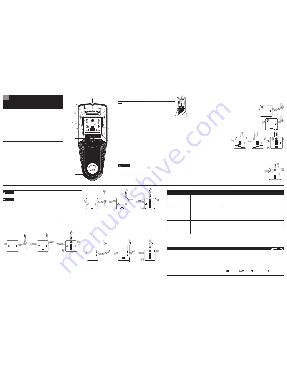
SpotLite
®
Pointer
Backlit LCD
AC Mode
Left Edge
Indicator
STUD SCAN
Mode (solid
stud icon) /
DEEPSCAN
®
Mode (flashing
stud icon)
Thermal Sensor
(back of unit)
Mode Button
Battery Door
(back of unit)
Center
Indication
Thermal
Mode
Signal
Strength
Indicator
Battery
Strength
Indicator
Right Edge
Indicator
Target
Indication
Bars
WARNING
WARNING
A
B
C
A
B
C
1
2
3
A
B
C
7. HELPFUL HINTS
(See also Section 2, OPERATING TIPS)
*Wood studs may only detect to 1
1
⁄
2
in. (38 mm) deep.
LIMITED 1 YEAR WARRANTY
Zircon Corporation, (“Zircon”) warrants this product to be free from defects in materials and workmanship for two years
from the date of purchase. Any in-warranty defective product returned to Zircon*, freight prepaid with proof of purchase
date and $5.00 to cover postage and handling, will be repaired or replaced at Zircon’s option. This warranty is limited to
the electronic circuitry and original case of the product and specifically excludes damage caused by abuse, unreasonable
use or neglect. This warranty is in lieu of all other warranties, express or implied, and no other representations or
claims of any nature shall bind or obligate Zircon. Any implied warranties applicable to this product are limited to the
one year period following its purchase. IN NO EVENT WILL ZIRCON BE LIABLE FOR ANY SPECIAL, INCIDENTAL OR
CONSEQUENTIAL DAMAGES RESULTING FROM POSSESSION, USE OR MALFUNCTION OF THIS PRODUCT.
In accordance with government regulations, you are advised that: (i) some states do not allow limitations on how
long an implied warranty lasts and/or the exclusion or limitation of incidental or consequential damages, so the above
limitations and/or exclusions may not apply to you, and further (ii) this warranty gives you specific legal rights and you
may also have other rights which vary from state to state.
Return product freight prepaid with proof of purchase date (dated sales receipt) and $5.00 to cover postage
and handling, to:
Zircon Corporation
*Attn: Returns Department
1580 Dell Avenue
Campbell, CA 95008-6918 USA
Be sure to include your name and return address. Out of warranty service and repair, where proof of purchase
is not provided, shall be returned with repairs charged C.O.D. Allow 4 to 6 weeks for delivery.
Customer Service, 1-800-245-9265 or 1-408-963-4550
Monday–Friday, 8:00 a.m. to 5:00 p.m. PST
www.zircon.com • [email protected]
© 2016 Zircon Corporation • P/N 65765 • Rev E 05/16
Visit www.zircon.com/support for the most current instructions.
ACT, DeepScan, MultiScanner, OneStep, SpotLite, and Zircon are registered trademarks or trademarks of Zircon Corporation.
FCC Part 15 Class B Registration Warning
This device complies with Part 15 of FCC Rules. Operations subject to the following two conditions: (1) this device
may not cause harmful interference, and (2) this device must accept any interference received, including interference
that may cause undesired operation.
ZirconCorporation
ZirconTV
ZirconTools
|
ZirconToolPro
ZirconTools


