Zip HydroTap G4 BC100/75, Installation And Operating Instructions Manual
The Zip HydroTap G4 BC100/75 is a state-of-the-art water dispenser that provides instant boiling and chilled filtered water. To easily set up and operate this premium appliance, make sure to download the free Installation and Operating Instructions Manual from our website.
Share
Download


Reviews:
No comments
Related manuals for HydroTap G4 BC100/75
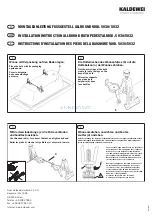
5030
Brand: Kaldewei Pages: 2

82951
Brand: Fackelmann Pages: 20

Freedom FM 080.00
Brand: RAVAK Pages: 28

942110C ABRUZZO
Brand: Fortis Pages: 2

115.725
Brand: Geberit Pages: 4

A05034
Brand: Nabis Pages: 4

KI-1931
Brand: baliv Pages: 40

RODAN RODX607
Brand: Franke Pages: 8

LUNEN BST-091
Brand: BATHSELECT Pages: 11

LI-VLV-4
Brand: C-TECH-I Pages: 5

SLS 02P
Brand: Sanela Pages: 6

AKER
Brand: MAAX Pages: 6
K-3674
Brand: Kohler Pages: 12

Brenna SLC-8212-STN-RP
Brand: Symmons Pages: 4

Duro Series
Brand: Symmons Pages: 7

Identity 6706
Brand: Symmons Pages: 18

Luni BeBa 28181
Brand: Better Bathrooms Pages: 12

Axor Allegroh 36415 Series
Brand: Hans Grohe Pages: 28


