background image

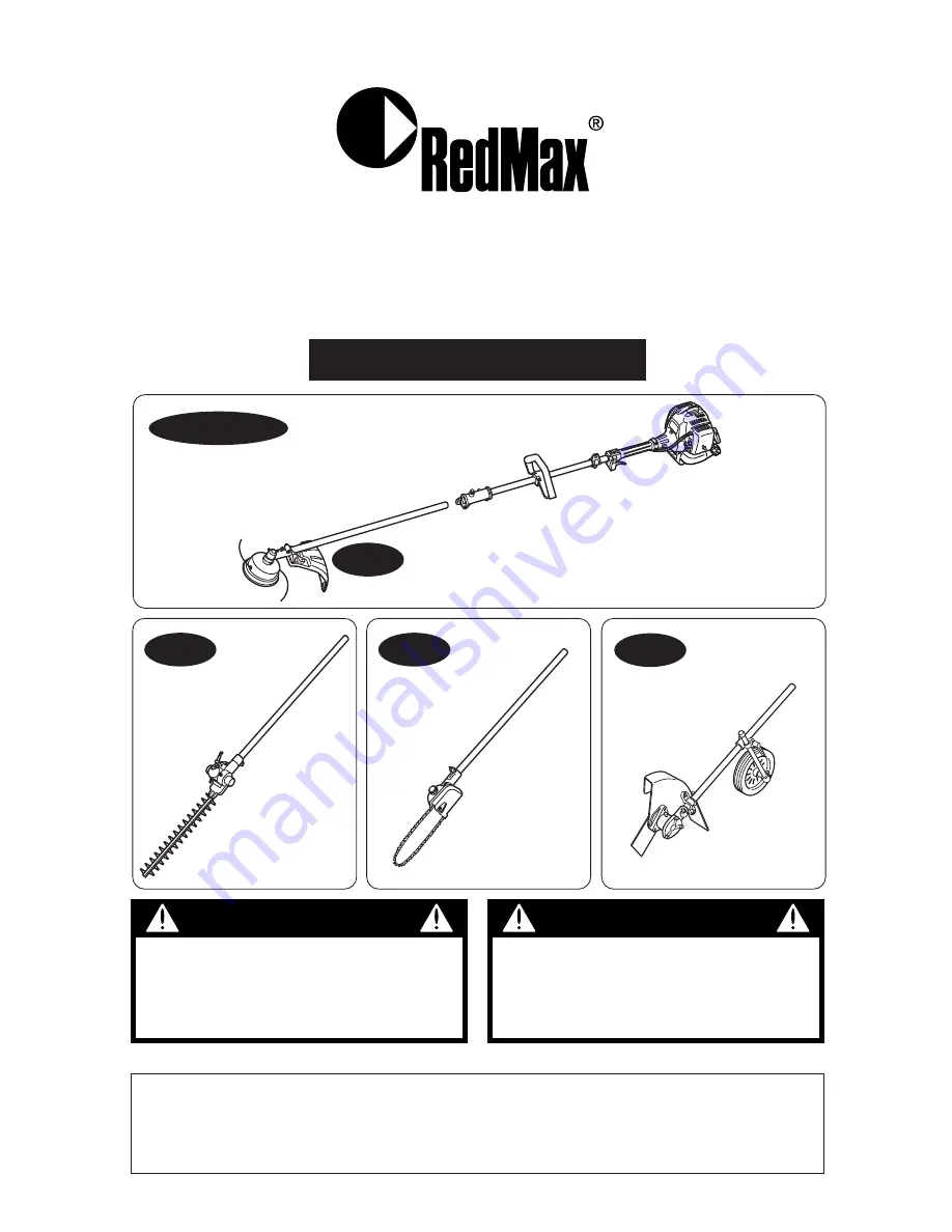
OWNER / OPERATOR MANUAL

EXtreme™

848-BP6-93A1 (501)

The engine exhaust from this product
contains chemicals known to the State
of California to cause cancer, birth
defects or other reproductive harm. 

WARNING

Before using our products, please
read this manual carefully to
understand the proper use of your
unit.

WARNING

EXZ-PU

302845  and up

EX-BC

302960  and up

EX-LRT

000531  and up

ENGINE UNIT  50100000  and up

EX-PS

000000  and up

EX-HE

000101  and up

APPLICABLE  SERIAL  NUMBERS : 

EX-BC

EX-PS

EX-LRT

EX-HE

EXZ2500S-BC

Summary of Contents for EXtreme EXZ2500S-BC

Page 1: ... birth defects or other reproductive harm WARNING Before using our products please read this manual carefully to understand the proper use of your unit WARNING EXZ PU 302845 and up EX BC 302960 and up EX LRT 000531 and up ENGINE UNIT 50100000 and up EX PS 000000 and up EX HE 000101 and up APPLICABLE SERIAL NUMBERS EX BC EX PS EX LRT EX HE EXZ2500S BC ...

Page 2: ...s which must be followed in order to prevent accidents which could lead to serious bodily injury or death This mark indicates instructions which must be followed or it leads to mechanical failure breakdown or damage This mark indicates hints or directions useful in the use of the product NOTE IMPORTANT WARNING CONTENTS 1 Parts location 3 2 Specifications 4 3 Warning labels on the machine 5 4 Symbo...

Page 3: ...ion switch 4 Throttle cable 5 Throttle lever 6 Throttle set button 7 Drive shaft housing 8 Knob bolt 9 Spark arrester 10 Starter knob 11 Fuel tank 12 Primer pump 13 Choke lever 14 Air cleaner cover 15 Debris guard 16 Gear case 17 Cutting line head 18 Blade 19 Gear case 20 Guide bar 21 Saw chain 22 Chain cover 23 Gear case 24 Wheel 25 Blade guard 26 Blade 3 ...

Page 4: ...ission Centrifugal clutch Rigid driveshaft Reduction ratio 4 0 Cutting head Type Reciprocating Double blade Tooth 28teeth Pitch 30 Effective cut width 16 in 40cm Angle adjust range 90 45 from cutting head position aligned shaft EX PS Overall size LxWxH 83 9 2100 x9 8 250 x12 2 310 in mm Dry weight w o bar and chain 11 1 lbs 5 05 kg Transmission Centrifugal clutch Rigid driveshaft Reduction ratio 0...

Page 5: ...ing label peel off or become soiled and impossible to read you should contact the dealer from which you purchased the product to order new labels and affix them in the required location s Never modify your machine We won t warrant the machine if you use the remodeled brushcutter or you don t observe the proper usage written in the manual WARNING IMPORTANT 3 Warning labels on the machine 5 ...

Page 6: ...osition less Position Bottom of the GEAR CASE 4 Symbols on the machine IMPORTANTENGINEINFORMATION ENGINE FAMILY 5KZXS 0254QR EM ENGINE DISPLACEMENT 25cc REFER TO OWNER S MANUAL FOR MAINTE NANCE SPECIFICATIONS AND ADJUSTMENTS MANUFACTURED THIS ENGINE CONFORMS TO 2005 U S EPA REGULATIONS FOR SMALL NONROAD ENGINES COMPLIANCE PERIOD CATEGORY A CE MOTEUR EST CONFORME A LA REGLEMENTATION U S EPA 2005 PO...

Page 7: ...ct you should wear proper clothing and protective equipment 1 Helmet 2 Ear protectors 3 Protection goggles or face protector 4 Thick work gloves 5 Non slip sole work boots 2 And you should carry with you 1 Attached tools 2 Properly reserved fuel 3 Spare blade 4 Things to notify your working area rope warning signs 5 Whistle for collaboration or emergency 6 Hatchet or saw for removal of obstacles 3...

Page 8: ...e the product properly and in a safe manner 2 When planning your work schedule allow plenty of time to rest Limit the amount of time over which the product is to be used continuously to somewhere around 30 40 minutes per session and take 10 20 minutes of rest between work sessions Also try to keep the total amount of work performed in a single day under 2 hours or less 1 If you don t observe the w...

Page 9: ...teners and fuel leakage Make sure that the cutting attachment is properly installed and securely fastened 4 Be sure the debris guard is firmly attached in place 5 Always use the shoulder strap Adjust the strap for comfort before starting the engine The strap should be adjusted so the left hand can comfortably hold the handlebar grip approximately waist high STARTING THE ENGINE 1 Keep bystanders an...

Page 10: ...part than the width of your shoulders so that your weight is distributed evenly across both legs and always be sure to maintain a steady even posture while working 2 Keep cutting attachment below waist level 3 Maintain the speed of the engine at the level required to perform cutting work and never raise the speed of the engine above the level necessary 4 If the unit start to shake or vibrate turn ...

Page 11: ...ther part or when replacing the oil or any lubricant always be sure to use only RedMax products or products which have been certified by RedMax for use with the RedMax product 4 In the event that any part must be replaced or any maintenance or repair work not described in this manual must be performed please contact a representative from the store nearest RedMax authorized servicing dealer for ass...

Page 12: ...here nearby before refueling 4 Wipe spilled fuel completely using a dry rag if any fuel spillage occurs during refueling 5 After refueling screw the fuel cap back tightly onto the fuel tank and then carry the unit to a spot 10 feet or more away from where it was refueled before turning on the engine TRANSPORTATION 1 When hand carrying the product cover over the cutting part if necessary lift up th...

Page 13: ...ner cover 2 Connect the end of the throttle wire to the joint on the top of the carburetor SE2 CONNECTING SWITCH WIRES Connect the switch wires between the engine and the main unit Pair the wires of the same color INSTALLING HANDLE EX BC EX LRT only SE3 Install the handle to the shaft tube and clamp it at a location that is comfortable to you 1 About 19 inches 48cm EX PS only SE4 Insert the grip t...

Page 14: ...E2 1 While locking the gear shaft by inserting the supplied tool into the upper holder on the gear box loosen and remove the hexagon nut left handed 2 Then screw in the cutting head to the gear shaft over the holders Hand tighten it securely BALANCE UNIT 1 Put on strap and attach unit to strap 2 Slide clamp up or down until unit balances with head just touching on the ground SE3 EX BC SE3 1 2 3 EX...

Page 15: ...rimming mechanism into which the screw is to be inserted with the hole on the main pipe and screw the screw firmly in 4 Using a wrench screw in the bolt provided to fix the trimming mechanism into place 1 Main pipe 2 Trimming mechanism 3 Screw hole 4 Screw 5 Fastening bolt BALANCE UNIT 1 Put on strap and attach unit to strap 2 Depending on the working posture slide clamp up or down until unit bala...

Page 16: ...screw in the bolt provided to fix the mechanism into place 1 Main pipe 2 Gear case 3 Screw hole 4 Fastening bolt 5 Bolt A standard package contains the items as shown below SE2 1 Guide bar 2 Saw chain 3 Gase case 4 Sprocket 5 Chain tension adjust screw 6 Nut 7 Chain tensioner nut 8 Chain cover Install the guide bar and the saw chain on the gear case as follows The saw chain has very sharp edges Us...

Page 17: ...ly with the bar tip held up SE6 TORQUE 8 9 11 7 N m 90 120 kg cm Then check the chain for smooth rotation and correct tension while moving it by hand If necessary readjustment 1 Tighten It is very important to maintain the proper chain tension Rapid wear of the guide bar or the chain coming off easily can be caused by improper tension Especially when using a new chain take good care of it since it...

Page 18: ...e with the provided 3 screws then clamp it to the shaft tube with 2 screws SE2 3 Place the blade between the cutter holders A and B while locking the gear shaft by putting the bar one of the tools provided through the key holes on the holder A and the gearcase Use the socket and the screwdriver as shown in the picture below to tighten the blade mounting bolt SE3 1 Blade mounting bolt Left handed 2...

Page 19: ... engine HOW TO MIX FUEL Pay attention to agitation 1 Measure out the quantities of gasoline and oil to be mixed 2 Put some of the gasoline into a clean approved fuel container 3 Pour in all of the oil and agitate well 4 Pour In the rest of gasoline and agitate IMPORTANT Gasoline is very flammable Avoid smoking or bringing any flame or sparks near fuel Make sure to stop the engine and allow it cool...

Page 20: ...OR YOUR ENGINE LIFE AVOID 1 FUEL WITH NO OIL RAW GASOLINE It will cause severe damage to the internal engine parts very quickly 2 GASOHOL It can cause deterioration of rubber and or plastic parts and disruption of engine lubrication 3 OIL FOR 4 CYCLE ENGINE USE It can cause spark plug fouling exhaust port blocking or piston ring sticking 4 Mixed fuels which have been left unused for a period of on...

Page 21: ...e engine running The cutting head will start rotating upon the engine starts 1 Feed fuel into the fuel tank and tighten the cap securely OP3 1 EX PS only Feed the chain oil into the oil tank and tighten the cap securely too OP3 2 1 Fuel 2 Chain oil 2 Rest the unit on a flat firm place Keep the cutting head off the ground and clear of surrounding objects as it will start rotating upon starting of t...

Page 22: ...come into contact with any obstacle when the engine starts OP8 Avoid pulling the rope to its end or returning it by releasing the knob Such actions can cause starter failures 7 Move the choke lever downward to open the choke And restart engine OP5 8 Allow the engine to warm up for a several minutes before starting operation 1 When restarting the engine immediately after stopping it leave the choke...

Page 23: ...e adjuster as required OP9 1 cable adjuster ADJUSTING IDLING SPEED OP10 1 When the engine tends stop frequently at idling mode turn the adjusting screw clockwise 2 When the cutting head keeps rotating after releasing the trigger turn the adjusting screw counter clockwise 1 idle adjusting screw Warm up the engine before adjusting the idling speed NOTE IMPORTANT 8 Operation 1 OP10 04 in 1 2mm 1 OP9 ...

Page 24: ... material being cut Heavy growth will require slower action than will light growth 4 Never swing the unit so hard as you are in danger of losing your balance or control of the unit 5 Try to control the cutting motion with the hip rather than placing the full workload on the arm and hands 6 Take precautions to avoid wire grass and dead dry long stem weeds from wrapping around the head shaft Such ma...

Page 25: ...oducts which have been certified by RedMax When sharpening removing or reattaching the blade be sure to wear thick sturdy gloves and use only proper tools and equipment to prevent injury SET UP 1 Detach the line head assembly completely OP2 2 Put on the blade making the marked side face the holder put on the outer holders and fasten the blade with the blade nut OP2 1 Cover 3540 13283 2 Holder 6019...

Page 26: ...any obstacle when the engine starts OP5 CUTTING METHOD a Use the front left side cutting b Guide the blade from your right to left with it tilted slightly to your left OP6 c When mowing a wide area start working from your left end to avoid interference of cut grass d The blade may be seized by weeds if the engine speed is too low or the blade cuts too deep into weeds Adjust the engine speed and cu...

Page 27: ...ome parallel to the ground OP8 Make sure to use shoulder strap and debris guard If not it is vary dangerous when you slip or lose your balance CONTROLLING BLADE BOUNCE Kick out can cause serious personal injury Carefully study this section It is important that you understand what causes kick out how you can reduce the chance of kick out and how you can remain in control of the unit if kick out doe...

Page 28: ... the chance of bounce e Avoid feeding the blade too rapidly The blade can bounce away from material being cut if the blade is fed faster than its cutting capability f Cut only from your right to your left g Keep your path of advance clear of material that has been cut and other debris 3 How you can maintain the best control a Keep a good firm grip on the unit with both hands A firm grip can help n...

Page 29: ...en using a grinder It is recommended that filing should be done by professionals Especially regarding filing the saw blade Leave it to the professionals TRANSPORTING THE UNIT When you finish cutting in one location and wish to continue work in another spot turn off the engine and lift up the unit and carry it paying attention fo the blade Never forget to place the protective cover over the blades ...

Page 30: ...imity with the blades Always wear work gloves made of leather or some other sturdy material when using the trimmer Always place the blade cover provided with the trimmer over the blades when not in use Falling branches may fall onto the face or into the eyes resulting in injuries scratches and cuts and for this reason you should always be sure to wear a helmet and face protector when using your tr...

Page 31: ...ate will speed oil consumption requiring more frequent checks on the oil reservoir To ensure sufficient lubrication It may be necessary to check the oil level more frequently than at fuel tank refills The guide bar and chain are lubricated automatically by a pump that operates whenever the chain rotates The pump is set at the factory to deliver a minimum flow rate but it can be adjusted in the fie...

Page 32: ...irection there are three incremental settings a Clockwise decrease lubrication b Counter clockwise increase lubrication c Middle Always wear work gloves made of leather or some other sturdy material when using the polesaw Falling branches may fall onto the face or into the eyes resulting in injuries scratches and cuts and for this reason you should always be sure to wear a helmet and face protecto...

Page 33: ...rown by the blade Do not adjust the wheel height or try to remove anything entangled to the blade with the engine running 1 Before starting the engine adjust the wheel height for desired cutting depth See page 21 2 Before starting a job plan your direction of travel so that you can always hold the edger on you right side and can walk on a hard surface as much as possible 3 When starting to edge ru...

Page 34: ... cooling vent clean muffler spark arrester cylinder exhaust port clean throttle lever ignition switch check operation replace if EX BC EX LRT cutting parts something s wrong EX HE gear case grease screws nuts bolts tighten replace not adjusting screws debris guard make sure to attach EX BC EX HE oiling port clean EX PS only guide bar clean EX PS only sprocket inspect replace EX PS only saw chain i...

Page 35: ...the fuel filter for blockage MA2 1 fuel filter SPARK PLUG Starting failure and mis firing are often caused by a fouled spark plug Clean the spark plug and check that the plug gap is in the correct range For a replacement plug use the correct type specified by RedMax MA3 REPLACEMENT PLUG IS A NGK CMR7A Note that using any spark plug other than those designated may result in the engine failing to op...

Page 36: ...d MA4 1 spark arrester INTAKE AIR COOLING VENT Never touch the cylinder muffler or spark plugs with your bare hands immediately after stopping the engine The engine can become very hot when in operation and doing so could result in severe burns When checking the machine to make sure that it is okay before using it check the area around the muffler and remove any wood chips or leaves which have att...

Page 37: ...n the part of the brushcutter MA6 1 cylinder 2 intake air cooling vent back PROCEDURES TO BE PERFORMED AFTER EVERY 100 HOURS OF USE 1 Remove the muffler insert a screwdriver into the vent and wipe away any carbon buildup Wipe away any carbon buildup on the muffler exhaust vent and cylinder exhaust port at the same time 2 Tighten all screws bolts and fittings 3 Check to see if any oil or grease has...

Page 38: ...n each part of the line MA2 4 Wind up the line in the correct direction as indicated on the spool MA3 5 Hook each end of the line in the slot on the edge of the spool and then put the ends through the eyelets on the housing Make sure that the spring and the washers are in place MA4 6 While holding the spool against the housing pull the line ends to release them from the slot 7 Line up the slot on ...

Page 39: ...rew too tightly may make it impossible for the blades to move Conversely not screwing in the screw tightly enough may make the blades of the trimmer feel dull and cause leaves and branches to become caught in the blades of the trimmer QUICK TIP If the blades become so worn down that it is no longer possible to eliminate the gap between them you should contact the authorized RedMax servicing dealer...

Page 40: ...nt the guide bar and check the oiling port for clogging MA1 1 Oiling port GUIDE BAR Remove sawdust in the bar groove and the oiling port MA2 1 Groove 2 Oiling port Type Sprocket nose Grease the nose sprocket from the feeding port on the tip of the bar MA3 1 Grease port 2 Sprocket ...

Page 41: ...s very important for smooth and safe operation to keep the cutters always sharp Your cutters need to be sharpened when Sawdust becomes powder like You need extra force to saw in The cut way does not go straight Vibration increases Fuel consumption increases Cutter setting standards Be sure to wear safety gloves Before filing Make sure the saw chain is held securely Make sure the engine is stopped ...

Page 42: ...e sure every cutter has the same length and edge angles as illustrated MA8 4 Cutter length 5 Filing angle 6 Side plate angle 7 Top plate cutting angle GEAR CASE The reduction gears are lubricated by multipurpose lithium based grease in the gearcase Supply new grease every 25 hours of use or more often depending on the job condition When adding lubricant use a grease gun to insert lubricant into th...

Page 43: ...rease in the gear case At every 20 hours of use supply the gear case with new grease Remove the cutter holders before installing new grease to arrange for old grease to exit When removing and installing the cutter holder a use care not to allow any dirt and dust entering in to the gear case NOTE MA1 43 ...

Page 44: ...ACTION fuel tank incorrect fuel or staled fuel drain it and with correct fuel carburetor adjustment screw out of normal range adjust to normal range muffler cylinder exhaust port carbon is built up wipe away air cleaner clogged with dust wash cylinder fin fan cover clogged with dust clean When your unit seems to need further service please consult with our RedMax service shop in your area 10 Stora...

Page 45: ...e contents described in the parts list may change due to improvement 5 The parts for the machine shall be supplied seven 7 years after the machine is discontinued It is possible that some specific parts may be subject to change of their delivery term and list price within the limit of seven 7 years after the machine is discontinued It is also possible that some parts may be available even after th...

Page 46: ...12 Parts list 46 Fig 1 EXZ PU S N 302845 and up ...

Page 47: ... CORD A T3002 12220 1 17 CORD B T3002 12230 1 18 TUBE T3002 12240 1 19 CABLE T3002 83100 1 20 HANGER ASSY 6420 17300 1 21 HANGER COMP 6420 17400 1 22 HANGER 9366 17110 1 23 CLAMP 9366 17120 1 24 SLEEVE 6420 17410 1 25 SCREW 0263 90525 1 26 PLATE NAME T3087 12511 1 27 HANDLE ASSY 6420 14100 1 28 HANDLE 6420 14311 1 29 CLAMP 6420 14320 1 30 SCREW 0263 90535 4 31 STRAP ASSY T3300 17100 1 32 TOOL SET ...

Page 48: ...12 Parts list 48 Fig 2 EX BC S N 302960 and up ...

Page 49: ...13350 1 19 WASHER 01641 20608 1 20 GUARD ASSY T3002 24001 1 21 GUARD COMP T3002 24101 1 22 BLADE T3002 24121 1 23 SCREW 0263 90516 1 24 NUT 3320 15310 1 25 PLATE 6489 24120 1 26 BOLT 01252 30514 4 27 TAP HEAD 4 PT104 1 28 CASE 6460 15123 1 29 CORD HOLDER 6460 15142 1 30 COVER 6460 15131 1 31 SPRING 6041 99162 1 32 TRIMMER LINE 6460 15180 1 33 PLATE large 3268 15150 1 34 PLATE small 3268 15170 1 35...

Page 50: ...Fig 3 ENGINE UNIT 50100000 and up 50 12 Parts list ...

Page 51: ...ion Part Number Q ty 73 SCREW adjuster 1918 81170 1 74 SCREW 1850 81530 4 75 WASHER 5500 81160 1 76 SCREW M5x60 0263 90560 2 77 MUFFLER ASSY 4810 15100 1 78 MUFFLER 4810 15111 1 79 ARRESTER 4810 15140 1 80 BOLT M5x50 01252 30550 2 81 GASKET T1501 15211 1 82 COVER ASSY 4810 31001 1 83 COVER COMP 4810 31101 1 84 COVER fan 4810 31110 1 85 DRUM 4810 31122 1 86 SNAPRING 04065 02812 1 87 BEARING 06002 0...

Page 52: ...12 Parts list 52 Fig 4 EX LRT S N 000531 and up ...

Page 53: ...6x15x2 0 6782 13650 1 35 BEARING 608 2RS 6598 13430 1 36 SNAP RING 04065 02212 1 37 SHAFT KIT T4008 06010 1 38 SHAFT 1 39 GEAR B 1 40 GEAR C T4008 13630 1 41 BOSS 1 42 SPRING T4008 13650 1 43 PLATE T4008 13660 1 44 WASHER T4008 13670 1 45 WASHER T4008 13680 1 46 NUT M6 0280 10605 1 47 WASHER 0290 20615 1 48 O RING P41 6598 13620 1 49 SNAP RING 04065 02612 1 50 BEARING 06004 06000 1 51 CASING B 678...

Page 54: ...12 Parts list 54 Fig 5 EX PS S N 000000 and up ...

Page 55: ...073 13800 1 22 COLLAR T3073 13820 2 23 VALVE T3073 13830 1 24 SCREW T3073 13860 2 25 OIL CAP ASSY T3073 13900 1 26 GASKET OIL CAP T3073 13920 1 27 GEAR SHAFT T3073 13370 1 28 BEVEL pinion T3073 13380 1 29 BEARING 06000 00609 1 30 BEARING 06002 00609 1 31 SNAP RING 3210 13330 1 32 SNAP RING 04065 02412 1 33 COLLAR T3073 13530 1 34 SPROCKET T3073 13540 1 35 LABEL T3073 13590 1 36 WASHER T3073 13350 ...

Page 56: ...12 Parts list 56 Fig 6 EX HE S N 000101 and up ...

Page 57: ...4121 1 30 CAP U 3257 14192 1 31 BOLT 01252 30522 2 32 BOLT 01252 30525 4 33 GUARD ASSY 6367 24001 1 34 GUARD COMP 6367 24101 1 35 GUARD 6367 24111 1 36 PLATE 6367 24120 1 37 PLATE 6367 24131 1 38 BOLT 0225 30512 2 39 CLAMP 5807 24120 1 40 BOLT 01252 30618 2 41 WASHER 0290 20615 2 42 BOLT 3350 31470 3 43 BLADE 6367 15110 1 44 COVER T3052 13610 1 45 WHEEL ASSY T3052 25001 1 46 BRACKET 6367 15230 1 4...

Page 58: ... PART THAT IS EQUIVALENT IN PERFORMANCE AND DULABILITY MAY BE USED IN NON WARRANTY MAINTENANCE OR REPAIRS AND SHALL NOT REDUCE THE WARRANTY OBLIGATION OF THE COMPANY THE COMPANY IS LIABLE FOR DAMAGES TO OTHER ENGINE COMPONENTS CAUSED BY THE FAILURE OF A WARRANTED PARTS STILL UNDER WARRANTY THE WARRANTY DOES NOT APPLY TO THOSE UNITS WHICH HAVE BEEN DAMAGED BY NEGLIGENCE OF INSTRUCTION LISTED IN THE...

Page 59: ... durabilité peut être utilisée pour l entretien hors garantie ou les réparations hors garantie et ce sans réduire l obligation de garantie incombant à la société La société sera tenue responsable des dommages aux autres composants du moteur causés par la défaillance de pièce s garantie s en période de garantie La garantie ne s applique pas aux unités endommagées par suite de négligence dans la mis...

Page 60: ...KOMATSU ZENOAH AMERICA INC 4344 Shackleford Road Suite 500 Norcross Georgia 30093 Printed in Japan ...

Reviews: