background image

ZGS 685
ZGS 645

Operating

instructions

Gas hob

Pуководство

по

эксплуатации

Upute za uporabu

Варочные

панели

Kuhala

CZ

EE

HR

KZ

LV

LT

RU

SI

SK

UA

Summary of Contents for ZGS 645

Page 1: ...ZGS 685 ZGS 645 Operating instructions Gas hob Pуководство по эксплуатации Uputezauporabu Варочные панели Kuhala CZ EE HR KZ LV LT RU SI SK UA ...

Page 2: ...2 ...

Page 3: ...ew appliance and we hope that you will consider our brand again when purchasing household appliances Please read this user manual carefully and keep it throughout the product life cycle as a reference document The user manual should be passed on to any future owner of the appliance ...

Page 4: ...Tips Environmental information Guide to Use the instructions This appliance complies with the following E E C Directives 2006 95 Low Voltage Directive 89 336 Electromagnetical Compatibility Directive 93 68 General Directives and subsequent modifications Itisveryimportantthatthisinstructionbookshouldbekeptsafelyforfutureconsultation Ifthe appliance should be sold or given to another person please e...

Page 5: ...rningshasbeengivenforthesafetyofyouandothers Wethereforeaskyoutocarefully read the procedures of installing and using this cooker Important safety information Child Safety This appliance has been designed to be operated by adults and children under supervision Young children must not be allowed to tamper with the controls or play near or with the oven This appliance is not intended for use by chil...

Page 6: ...rvice Under no circumstances should you attempt to repair the appliance yourself Repairs carried out by unexperienced persons may cause injury or serious malfunctioning Refer to your local Service Centre Always insist on genuine spare parts Environmental Information After installation please dispose of the packaging with due regard to safety and the environment When disposing of an old appliance m...

Page 7: ... supply would be interrupted Then check the flame is regular and adjust it as required If you cannot light the flame even after several attempts check the cap and crown are in the correct position In the absence of electricity ignition can occur without the electrical device in this case approach the burner with a flame push the re levant knob down and turn it anti clockwise until it reaches the m...

Page 8: ...saucepan which is smaller than the recommended size the flame will spread beyond the bottom of the vessel causing the handle to overheat Prolonged cooking with potstones earthenware pans or cast iron plates is inadvisable Also do not use aluminium foil to protect the top during use Make sure pots do not protrude over the edges of the cooktop and that they are centrally positioned on the rings in o...

Page 9: ... be used with caution if the marks are particularly difficult to remove After cleaning be sure to wipe dry with a soft cloth Frequently wash the caps and the crowns with hot soapy water carefully taking away any built up of food The pan supports After cleaning make sure that the pan sup ports are correctly positioned To make burners work properly ensure that pan supports are placed in a way that t...

Page 10: ...ucts are recommended For stainless steel hobs use a proprietary stainless steel cleaner For other hobs use Hob Brite or Bar Keepers Friend Do not leave acid or alkaline substances e g vinegar salt lemon juice etc on the cooktop The Ignition electrode The electric ignition is obtained through a ceramic electrode with a metal electrode Fig C Keep these components very clean to avoid difficult lighti...

Page 11: ...xiliary burner 1 0 kW Category II2H3B P Gas supply natural gas G20 2H 20 mbar Gas connection G 1 2 Electric supply 230 V 50 Hz Appliance class 3 Hobdimensions Width 594 mm Depth 510 mm Cutoutdimensions Width 560 mm Depth 480 mm By pass diameters Burner Ø By pass in 1 100 mm Auxiliary 28 Semi rapid 32 Rapid ZGS645 42 Triple crown ZGS 685 56 ...

Page 12: ...5 96 0 190 71 145 143 Rapid 3 0 burner natural gas 0 75 119 0 285 86 204 200 ZGS 645 2 8 LPG Triplecrown burner 4 0 1 2 146 0 381 98 291 286 ZGS 685 Gas burners G20 13 mbar only Russia NORMAL REDUCED NORMAL POWER POWER POWER BURNER NATURAL GAS G20 13 mbar kW kW inj m3 h 100 mm Auxiliary burner 0 9 0 33 80 0 095 Semi rapid burner 1 4 0 45 105 0 148 Rapid burner ZGS645 1 9 0 75 120 0 20 Triple crown...

Page 13: ...n The flexible pipe should be made ready for use in such a way that nowhere it can reach overtemperature other than room temperature higher than 30 C if the flexible pipe to reach the cock must run behind the range it must be installed as shown in picture it is no longer than 1500 mm it shows no throttles it is not subject to traction or torsion it doesn t get in touch with cutting edges or corner...

Page 14: ...he pipe but replace it IMPORTANT Once installation is complete check the perfectseal of every pipe fitting using a soapy solution never a flame A Ramp with ending nut B Seal C Adjustable connection D Rubber pipe holder for liquid gas D Natural gas Liquid gas ...

Page 15: ...n force B Adjustmentofminimumlevel To adjust the minimum level of the burners proceed as follows Light the burner Turn the knob on the minimum position Remove the knob With a thin screwdriver adjust the by pass screw positioned in the centre of the gas tap control shaft see Fig 6 If changing from natural gas 20 mbar to liquid gas completely tighten the adjustment screw in If changing from liquid g...

Page 16: ...h between the appliance and the electricity supply with a minimum gap of 3 mm between the switch contacts and of a type suitable for the required load in compliance with the current rules The connection cable has to be placed in order that in each part it cannot reach a temperature 50 C higher than room temperature The brown coloured phase cable fitted in the terminal block contact marked with L m...

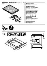
Page 17: ...ust be placed at 650 mm minimum from the hob Fitting the hob to the worktop Carry out the building in of the hob as follows 1 Place the seals supplied with the hob on the front edge of the cut out Then place them at 11 mm from the side edges and at 10 mm from the rear edge as shown in the diagram taking care that the seals meet without overlapping 2 Place the hob in the cut out taking care that it...

Page 18: ...x the hob with the relevant fixing clamps supplied with the injectors kit see diagram When the screws have been tightened the excess seal can be removed The edge of the hob forms a double seal which prevents the ingress of liquids ...

Page 19: ...easy access if a technical assistance intervention is needed Kitchen unit with oven The hob recess dimensions must comply the indication given in Figs 11 and 12 and must be provided with brackets to allow a continuous supply of air To avoid overhating the building in should be carried out as shown in Figs 13 e 14 The hob s electric connection and the oven s one must be carried out separately both ...

Page 20: ...nt issued by the seller of the appliance Theapplianceguaranteeisforthesameperiodandtothesameextentforlabourandpartsasexists in your new country of residence for this particular model or range of appliances The appliance guarantee is personal to the original purchaser of the appliance and cannot be transferred to another user TheapplianceisinstalledandusedinaccordancewithinstructionsissuedbyElectro...

Page 21: ...21 ...

Reviews: