background image

INSTALLATION, OPERATION, MAINTENANCE

MILLENNIUM

TM

AIR-COOLED SCREW LIQUID CHILLERS

Supersedes: Nothing

Form 201.18-NM2 (1199)

MILLENNIUM

TM

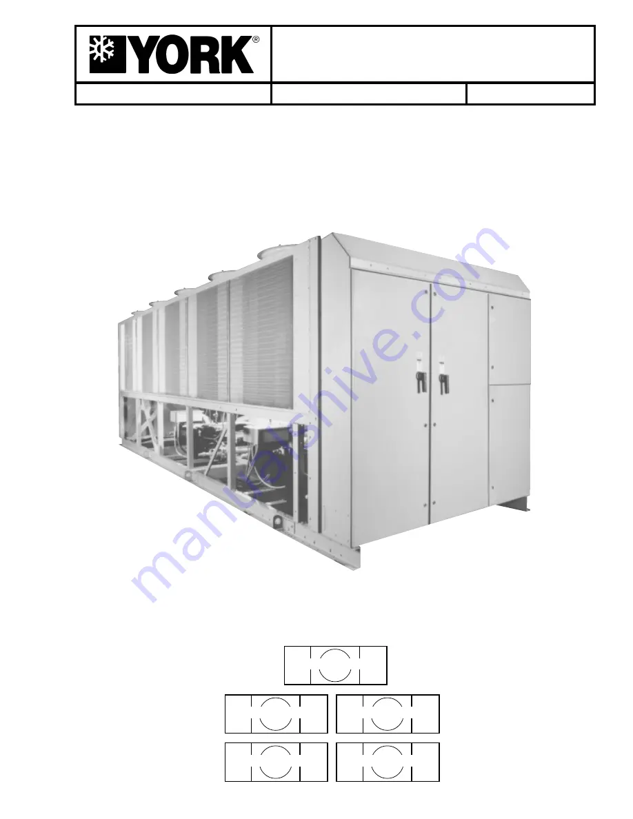
YCAS AIR-COOLED SCREW LIQUID CHILLER

YCAS0373 – YCAS0653

YCAS 2-SYSTEM With EPROM

(Standard, Brine & Metric Models Combined)

031-01798-001

YCAS 3-SYSTEM EPROM

+

I/O Board EPROM

031-02018-001

031-01798-002

YCAS 4-SYSTEM EPROM

+

I/O Board EPROM

031-02018-001

031-01798-002

Microprocessor Board

Microprocessor Board

28971AR

Summary of Contents for MILLENNIUM YCAS

Page 1: ...ILLENNIUM TM YCAS AIR COOLED SCREW LIQUID CHILLER YCAS0373 YCAS0653 YCAS 2 SYSTEM With EPROM Standard Brine Metric Models Combined 031 01798 001 YCAS 3 SYSTEM EPROM I O Board EPROM 031 02018 001 031 0...

Page 2: ...n 26 Unit Nomenclature Nameplate Engineering Data 27 SECTION 3 HANDLINGANDSTORAGE Delivery and Storage 28 Inspection 28 Moving the Chiller 28 SECTION 4 INSTALLATION Location Requirements 29 Outdoor In...

Page 3: ...sions 70 YCAS0373 YCAS0503 70 YCAS0543 YCAS0623 72 YCAS0653 74 Operating Weights Aluminum Fin Coils 76 Isolator Selection Aluminum Fin Coils 77 Operating Weights Copper Fin Coils 78 Isolator Selection...

Page 4: ...y 119 4 PRINT KEYS 120 4 1 General 120 4 2 Oper Data Key 120 4 3 Operating Data Local Display Messages 120 4 4 Operating Data Remote Printout 122 4 5 History Key 123 4 6 Fault History Data Local Displ...

Page 5: ...ront Inside View Wye Delta Start 63 FIG 18 Connection Diagram 64 FIG 19 Detail A 65 FIG 20 Connection Diagram System Wiring 66 FIG 21 Sensor Connection 66 FIG 22 Compressor Systems 1 2 66 FIG 23 Compr...

Page 6: ...indi vidual shall also be familiar with and comply with all applicable governmental standards and regulations per taining to the task in question SAFETY SYMBOLS The following symbols are used in this...

Page 7: ...pplicability of these documents to the equip ment in question If there is any question in the mind of operating service personnel as to the applicability of these documents then prior to working on th...

Page 8: ...ecify the unit model serial number order number and run hours starts These de tails are printed on the unit identification plate The unit warranty will be void if any modification to the unit is carri...

Page 9: ...the equipment The unit must not be operated outside the design pa rameters specified in this manual Structural Support Structural support of the unit must be provided as indi cated in these instructio...

Page 10: ...ex ample does pose a risk of asphyxiation in confined or enclosed spaces and attention should be given to good ventilation For more comprehensive information on safety precautions for use of refriger...

Page 11: ...hat R22 does not represent a carcinogenic hazard to humans Occupational Recommended limit 1000 ppm v v 8 hr TWA 1250 ppm v v 12 hr TWA Exposure Limits Stability Unstable Conditions to Avoid Use in pre...

Page 12: ...en highly recommended Section 4 PHYSICAL DATA Appearance Clear liquid gray to yellow or light brown tint BoilingPoint 650 F Vapor Pressure 0 01 mmHg 20 C Specific Gravity water 1 0 94 0 97 Volatiles P...

Page 13: ...atory Protection Use in well ventilated area Ventilation Local exhaust Protective Gloves Strongly recommended especially for prolonged exposure Eye Face Protection Goggles Firefighters should use NIOS...

Page 14: ...avy gauge galvanized steel All external structural parts are coated with Desert Sand baked on enamel powder paint This provides a finish which when subjected to ASTM B117 500 hour 5 salt spray conditi...

Page 15: ...backspin due to system refriger ant pressure gradients during shutdown Motor cooling is provided by suction gas from the evapo rator flowing across the motor Redundant overload pro tection is provide...

Page 16: ...system The de sign working pressure of the economizer is 31 bar 450 PSIG The economizer liquid supply solenoid is acti vated on start up coincident with the liquid line solenoid after pumpdown The eco...

Page 17: ...slide valve against the spring pressure to provide stable smooth loading Power and Control Panel All controls and motor starting equipment are factory wired and function tested The panel enclosures a...

Page 18: ...h operating conditions The software is stored in non volatile memory EPROM to eliminate chiller failure due to AC power failure The Programmed Setpoint is stored in lithium battery backed memory Motor...

Page 19: ...d that a YORK Ser vice Technician or the YORK factory be consulted before changing these settings for any reason since damage to the compressor could result Changes should never be made unless it is v...

Page 20: ...0 0 1 0 0 0 73 0 1 0 0 1 0 0 1 74 0 1 0 0 1 0 1 0 75 0 1 0 0 1 0 1 1 76 0 1 0 0 1 1 0 0 77 0 1 0 0 1 1 0 1 78 0 1 0 0 1 1 1 0 79 0 1 0 0 1 1 1 1 80 0 1 0 1 0 0 0 0 81 0 1 0 1 0 0 0 1 82 0 1 0 1 0 0 1...

Page 21: ...0 0 0 1 114 0 1 1 1 0 0 1 0 115 0 1 1 1 0 0 1 1 116 0 1 1 1 0 1 0 0 117 0 1 1 1 0 1 0 1 118 0 1 1 1 0 1 1 0 119 0 1 1 1 0 1 1 1 120 0 1 1 1 1 0 0 0 121 0 1 1 1 1 0 0 1 122 0 1 1 1 1 0 1 0 123 0 1 1 1...

Page 22: ...1 0 1 1 156 1 0 0 1 1 1 0 0 157 1 0 0 1 1 1 0 1 158 1 0 0 1 1 1 1 0 159 1 0 0 1 1 1 1 1 160 1 0 1 0 0 0 0 0 161 1 0 1 0 0 0 0 1 162 1 0 1 0 0 0 1 0 163 1 0 1 0 0 0 1 1 164 1 0 1 0 0 1 0 0 165 1 0 1 0...

Page 23: ...0 1 0 0 197 1 1 0 0 0 1 0 1 198 1 1 0 0 0 1 1 0 199 1 1 0 0 0 1 1 1 200 1 1 0 0 1 0 0 0 201 1 1 0 0 1 0 0 1 202 1 1 0 0 1 0 1 0 203 1 1 0 0 1 0 1 1 204 1 1 0 0 1 1 0 0 205 1 1 0 0 1 1 0 1 206 1 1 0 0...

Page 24: ...rocessor from Terminal 9 The 1TR SYS 1 or 2TR SYS 2 contacts open de energizing 1S SYS 1 or 2S SYS 2 1M SYS 1 or 3M SYS 2 remain energized through interlocking contacts 1M SYS 1 or 3M SYS 2 Opening of...

Page 25: ...rminal blocks in the power compartments Single Point Power Connection without Circuit Protection A single point supply circuit with field provided protec tion is connected to a factory provided termin...

Page 26: ...ld mounted Louvered panels and wired guards Louvered pan els mounted over the exterior condenser coil faces and heavy gauge welded wire mesh guards mounted around the bottom of the unit Factory or fie...

Page 27: ...s Brkr L Ext Handles Individual System Breaker Lockable External Handle 16 17 18 19 20 21 22 23 24 25 26 27 28 29 30 31 32 33 34 35 3637 POWER FIELD CONTROLS FIELD COMPRESSOR PIPING FIELD M D X M B Y...

Page 28: ...ECTION Remove any transit packing and inspect the unit to en sure that all components have been delivered and that no damage has occurred during transit If any damage is evident it should be noted on...

Page 29: ...nd must be at least 120 mm 4 3 4 wide at the contact points This will allow vibra tion isolators to be fitted if required Any ductwork or attenuators fitted to the unit must not have a total static pr...

Page 30: ...or the cooler must not be ex ceeded at any time Refer to the Tech nical Data Section for details The liquid must enter the cooler by the inlet connection The inlet connection for the cooler is at the...

Page 31: ...trol system power supply During risk of freezing the control sys tem should be left switched on to provide the freeze protection function unless the liquid systems have been drained Any debris left in...

Page 32: ...speci fied by local regulations table internal diameter depends on the length of pipe required and is given by the fol lowing formula D5 1 447 x L Where D minimum pipe internal diameter L length of p...

Page 33: ...re that no eddy currents are set up in the power panel the cables forming each 3 phase power supply must enter via the same cable entry All sources of supply to the unit must be taken via a common poi...

Page 34: ...se to indicate that a system is running Alarm Contacts Each system has a voltage free change over contact which will operate to signal an alarm condition when ever a system locks out or there is a pow...

Page 35: ...BREAKERS FIG 8 PANEL LAYOUTS CONTROL PANEL RELAY BOARDS I O EXPANSION BOARD CUSTOMER CONNECTIONS Flow Switch Alarm Run 115VAC supply etc MICROPROCESSOR CIRCUITBOARD 28965A POWER PANELS FANCIRCUIT BRE...

Page 36: ...Alarm Run 115VAC supply etc MICROPROCESSOR CIRCUITBOARD 28965A CUSTOMER CONNECTIONS Print Temperature PWM Current PWM Flow Switch System No 1 Run System No 2 Run 13 13 13 13 13 14 15 16 17 18 19 23 24...

Page 37: ...he fan overloads settings are correct for the type of fan fitted Supply Voltage Verify that the site voltage supply corresponds to the unit requirement and is within the limits given in the Tech nical...

Page 38: ...ion outside of these limits is undesirable and could cause damage Flow Switch Verify a chilled water flow switch is correctly fitted in the customer s pipework on the cooler outlet and wired into the...

Page 39: ...be replaced by a solid column of liquid Fan Rotation As discharge pressure rises the condenser fans oper ate in stages to control the pressure Verify that the fan operation is correct for the type of...

Page 40: ...perations are fully automatic After an initial period at minimum capacity on the lead compressor the control system will adjust the unit load depending on the chilled liquid temperature and rate of te...

Page 41: ...RON NUMBER TEMPERATURE C L S 3 CONDENSER C YCAS MIN 1 MAX 2 MIN MAX MIN MAX 0373 4 4 13 0 9 3 37 8 17 7 51 7 0403 4 4 13 0 10 7 37 8 17 7 51 7 0453 4 4 13 0 11 5 37 8 17 7 51 7 0503 4 4 13 0 11 5 37 8...

Page 42: ...ch allows for an increase in pressure drop of up to 15 above the design value given above Debris in the water may also cause additional pressure drop When using glycol solutions pressure drops are hig...

Page 43: ...0373EC 1249 9 38 0403EC 1351 11 38 0453EC 1499 12 47 0503EC 1700 12 47 0543EC 1802 13 47 0573EC 1900 14 47 0623EC 1999 14 47 0653EC 2101 16 47 AIR STANDARD FANS 18 46 ENTERING HIGH PRESS FANS 18 46 C...

Page 44: ...12 512 512 Condenser Fans Number Ckt 1 Ckt 2 3 3 3 3 3 3 3 3 4 4 4 4 4 4 5 5 Number Ckt 3 Ckt 4 Standard Fans Fan Motor HP kW 2 1 6 2 1 6 2 1 6 2 1 6 2 1 6 2 1 6 2 1 6 2 1 6 Fan Motor speed rev sec 15...

Page 45: ...512 512 512 512 512 512 Condenser Fans Number Ckt 1 Ckt 2 3 3 3 3 3 3 3 3 4 4 4 4 4 4 5 5 Number Ckt 3 Ckt 4 Standard Fans Fan Motor HP kW 2 1 6 2 1 6 2 1 6 2 1 6 2 1 6 2 1 6 2 1 6 2 1 6 Fan Motor sp...

Page 46: ...0 500 2 1 500 3 2 0 400 0543 380 387 400 400 450 2 2 300 2 3 0 250 0573 380 455 600 500 500 2 1 500 3 2 0 400 0623 380 493 600 500 600 2 1 500 3 2 0 400 0653 380 464 600 500 500 2 1 500 3 2 0 400 Mode...

Page 47: ...4 4 17 1 0573 380 227 250 300 350 1 500 6 AWG 350 2 3 0 250 168 309 979 4 4 4 17 1 0623 380 247 250 300 400 1 500 6 AWG 350 2 3 0 250 183 309 979 4 4 4 17 1 0653 380 232 250 300 350 1 500 6 AWG 350 2...

Page 48: ...50 150 150 150 150 113 150 105 105 105 105 80 105 MAX AMPS 492 428 259 214 193 171 492 428 259 214 193 171 338 294 178 147 135 118 FAN DATA FANTYPE NOMINAL POWER FULL LOAD AMPS LOCKED ROTOR AMPS kW FL...

Page 49: ...or lugs which are available per phase Actual wire size and number of wires per phase must be determined based on ampacity and job requirements using N E C wire sizing information The above recommenda...

Page 50: ...ER SUPPLY WITH INTERNAL UNIT CIRCUIT BREAKERS Suitable for Y D D D D D Start and Across The Line Start LD04107 50 SEE NOTE 2 Optional Field Provided 115 1 MicroPanel Supply Suitable for Y D D D D D St...

Page 51: ...IT BREAKER LD04109 50 Suitable for Across The Line Start Only SEE NOTE 2 Optional Field Provided 115 1 MicroPanel Supply NOTES 1 Dashed Line indicates Field Provided Wiring 2 The above recommendations...

Page 52: ...ns on page 55 5 To stop unit Emergency Stop with contacts other than those shown install the stop contact between 5 and 1 If a stop device is not installed a jumper must be connected between terminals...

Page 53: ...53 YORK INTERNATIONAL FORM 201 18 NM2 WIRING DIAGRAM ACROSS THE LINE START 7...

Page 54: ...54 YORK INTERNATIONAL FIG 12 CONTINUED ELEMENTARY DIAGRAM Technical Data...

Page 55: ...ired through motor contactor aux iliary contacts must be sup pressed with YORK P N 031 00808 000 suppressor across the relay contactor coil Any contacts connected to flow switch inputs or BAS inputs o...

Page 56: ...56 YORK INTERNATIONAL FIG 13 POWER PANEL FRONT INSIDE VIEW ACROSS THE LINE START Technical Data...

Page 57: ...57 YORK INTERNATIONAL FORM 201 18 NM2 LD03280 FIG 14 ELECTRONIC PANEL FRONT INSIDE VIEW ACROSS THE LINE START 7...

Page 58: ...ns on page 61 5 To stop unit Emergency Stop with contacts other than those shown install the stop contact between 5 and 1 If a stop device is not installed a jumper must be connected between terminals...

Page 59: ...59 YORK INTERNATIONAL FORM 201 18 NM2 WIRING DIAGRAM WYE DELTA START LD03229 FIG 15 CONT D 7...

Page 60: ...60 YORK INTERNATIONAL FIG 15 CONTINUED ELEMENTARY DIAGRAM Technical Data...

Page 61: ...d through motor contactor aux iliary contacts must be sup pressed with YORK P N 031 00808 000 suppressor across the relay contactor coil Any contacts connected to flow switch inputs or BAS inputs on t...

Page 62: ...62 YORK INTERNATIONAL FIG 16 POWER PANEL FRONT INSIDE VIEW WYE DELTA START Technical Data...

Page 63: ...63 YORK INTERNATIONAL FORM 201 18 NM2 LD03280 FIG 17 ELECTRONIC PANEL FRONT INSIDE VIEW WYE DELTA START 7...

Page 64: ...64 YORK INTERNATIONAL LEGEND FIGS 12 THROUGH 16 LD03281 CONNECTION DIAGRAM ELECTRIC BOX DXST DIRECT DRIVE FIG 18 CONNECTION DIAGRAM Technical Data...

Page 65: ...65 YORK INTERNATIONAL FORM 201 18 NM2 LD03282 LD03283 LD03284 FIG 19 DETAIL A see pages 54 59 7...

Page 66: ...66 YORK INTERNATIONAL CONNECTION DIAGRAM SYSTEM WIRING LD03230 LD03231 LD03232 FIG 20 CONNECTION DIAGRAM SYSTEM WIRING FIG 21 SENSOR CONNECTION FIG 22 COMPRESSORS SYSTEMS 1 2 Technical Data...

Page 67: ...67 YORK INTERNATIONAL FORM 201 18 NM2 COMPRESSOR TERMINAL BOX LD03233 FIG 23 COMPRESSOR TERMINAL BOXES 7...

Page 68: ...68 YORK INTERNATIONAL FIG 24 DETAIL B Technical Data...

Page 69: ...69 YORK INTERNATIONAL FORM 201 18 NM2 3 4 5 6 3 4 5 6 7 8 5 6 3 4 7 8 9 10 11 12 9 10 7 8 5 6 3 4 FIG 25 DETAIL C 7...

Page 70: ...clearances indicated below resulting in unpre dictable air flow patterns and possible diminished performance YORK s unit controls will optimize operation without nuisance high pressure safety cutout...

Page 71: ...GRAVITY Copper YCAS X Y Z 0373 2331 7 1127 8 960 1 0403 2331 7 1127 8 960 1 0453 2331 7 1135 4 955 0 0503 2331 7 1135 4 955 0 CENTER OF GRAVITY Alum YCAS X Y Z 0373 2324 1 1130 3 889 0 0403 2324 1 11...

Page 72: ...clearances indicated below resulting in unpre dictable air flow patterns and possible diminished performance YORK s unit controls will optimize operation without nuisance high pressure safety cutout...

Page 73: ...NTER OF GRAVITY Alum YCAS X Y Z 0543 2717 8 1087 1 914 4 0573 2717 8 1097 3 914 4 0623 2717 8 1097 3 914 4 2718 CENTER OF GRAVITY Copper YCAS X Y Z 0543 2755 9 1092 2 988 1 0573 2753 4 1097 3 988 1 06...

Page 74: ...indicated below resulting in unpre dictable air flow patterns and possible diminished performance YORK s unit controls will optimize operation without nuisance high pressure safety cutout however the...

Page 75: ...75 YORK INTERNATIONAL FORM 201 18 NM2 LD03004 CENTER OF GRAVITY Alum YCAS X Y Z 0653 3032 8 1097 3 965 2 CENTER OF GRAVITY Copper YCAS X Y Z 0653 3106 4 1099 8 1041 4 LD03005 7...

Page 76: ...544 3 1 17 29 7 Purple CP 2 27 1500 680 4 1 06 26 9 Orange CP 2 28 1800 816 4 1 02 25 9 Green CP 2 31 2200 997 9 0 83 21 0 Gray CP 2 32 2600 1179 3 0 74 18 7 White CP 2 35 3000 1360 8 0 70 17 7 Gold A...

Page 77: ...ACK RED 0453 RED BLACK RED BLACK BLACK RED 0503 RED BLACK RED BLACK BLACK RED 0543 RED BLACK RED BLACK RED BLACK BLACK BLACK 0573 RED BLACK RED BLACK RED BLACK BLACK BLACK 0623 RED BLACK RED BLACK RED...

Page 78: ...equipment to isolators when used under out door equipment exposed to wind forces 3 Lubricate threads of adjusting bolt Loosen hold down bolts to allow for isolator adjustment 4 Block the equipment 1...

Page 79: ...D RED 0453 RED RED RED BLACK RED RED 0503 RED RED RED BLACK RED RED 0543 RED BLACK RED BLACK RED BLACK RED RED 0573 RED BLACK RED BLACK RED BLACK RED RED 0623 RED BLACK RED BLACK RED BLACK RED RED 065...

Page 80: ...3 or RD 3 139 7 85 8 73 2 63 5 12 7 104 8 14 4 6 3 5 5 3 375 2 875 2 5 0 5 4 125 0 563 0 25 R 4 or RD 4 158 7 117 6 69 8 76 2 12 7 127 0 14 4 9 6 6 25 4 625 2 75 3 0 0 5 5 0 0 563 0 375 LD04033 LD0473...

Page 81: ...1 2 4 1 4 10 1 2 3 4 1000 1628 11NC 5 8 AWMR 2 17 6 3 3 4 1 7 1 2 3 3 4 1 2 7 1 2 5 8 14 1 2 7 1 4 17 7 8 1000 1628 10NC 3 4 AWMR 4 17 8 4 7 8 1 1 4 7 1 2 3 3 4 3 4 7 3 4 3 4 14 1 2 7 1 4 17 7 8 1000...

Page 82: ...82 YORK INTERNATIONAL ISOLATOR LOCATIONS MODELS YCAS 0373 0403 0453 0503 LD03081 MODELS YCAS 0543 0573 0623 0653 LD03019 FIG 28 ISOLATOR LOCATIONS Technical Data...

Page 83: ...M 201 18 NM2 1 3 m 48 2 m 72 2 m 72 2 m 72 CLEARANCES Notes No obstructions allowed above the unit Only one adjacent wall may be higher than the unit Adjacent units should be 3 meters 10 feet apart LD...

Page 84: ...ugh the cooler shell Low pressure vapor enters the compressor where pres sure and superheat are increased High pressure vapor is passed through the oil separator where compressor oil is removed and re...

Page 85: ...85 YORK INTERNATIONAL FORM 201 18 NM2 PROCESS AND INSTRUMENTATION DIAGRAM LD03486 FIG 31 PROCESS AND INSTRUMENTATION DIAGRAM 7...

Page 86: ...SURE BOT OIL TEMPERATURE BSP SUCTION PRESSURE CCCV COMPRESSOR CAPACITY CONTROL VALVE ECH CRANK CASE HEATER EEH EVAPORATOR HEATER SHPI HIGH PRESSURE CUT OUT STS SUCTION TEMPERATURE SENSOR RFTS REFRIGER...

Page 87: ...DEDHOLE OIL HEATER ECONOMIZER GAS IN DISCHARGE CASE OILINLET FROMCONDENSER CODINGCOIL DISCHARGE GAS OUT OILFILTER BLEED EVACUATION POINT OILFILTER COVERPLATE CAPACITY CONTROL SOLENOID CAPACITY CONTROL...

Page 88: ...88 YORK INTERNATIONAL COMPRESSOR COMPONENTS CONT D FIG 34 COMPRESSOR COMPONENTS LD03669 Technical Data...

Page 89: ...89 YORK INTERNATIONAL FORM 201 18 NM2 COMPRESSOR COMPONENTS CONT D FIG 35 COMPRESSOR COMPONENTS LD03670 7...

Page 90: ...90 YORK INTERNATIONAL COMPRESSOR COMPONENTS CONT D FIG 36 COMPRESSOR COMPONENTS LD03671 Technical Data...

Page 91: ...01 18 NM2 COMPRESSOR COMPONENTS CONT D FIG 37 COMPRESSOR COMPONENTS LD03672 7 O RING MOTOR ROTOR MALE ROTOR LOCKING KEY MALE ROTOR FEMALEROTOR O RING RELIEF VALVE ECONOMIZERPLUG SUPPORTRINGS SLIDE VAL...

Page 92: ...22 BEARING CLAMP NUT 23 BEARING SPACER SLEEVE 24 BEARING PRELOAD SPRING 25 O RING 26 BEARING BORE PLUG 27 DISCHARGE COVER 28 BEARING BORE PLUG 29 BEARING PRELOAD SPRING 30 BEARING SPACER SLEEVE 31 BEA...

Page 93: ...mp sensors are inserted completely in their respective wells and are coated with heat conductive compound q 14 Assure that evaporator TXV bulbs are strapped onto the suction lines at 4 or 8 o clock po...

Page 94: ...d lasts for only a short time q 4 Check the system operating parameters Do this by selecting various displays such as pressures and temperatures Compare these to test gauge readings PANEL CHECKS Power...

Page 95: ...SYS 1 SYS 2 SYS 3 SYS 4 Liq Line Press ____ ____ ____ ____ KPA PSIG Temp ____ ____ ____ ____ C F Liq Line Temp ____ ____ ____ ____ C F Subcooling ____ ____ ____ ____ C F After the subcooling is set th...

Page 96: ...not more than one turn at a time allowing suffi cient time approximately 15 minutes between adjust ments for the system and the thermal expansion valve to respond and settle out Assure that superheat...

Page 97: ...rammed data as well as fault history data from recent safety shutdowns ON OFF ROCKER SWITCH This switch shuts down the entire chiller when placed in the OFF position The switch must be ON for the chil...

Page 98: ...m annunciation YCAS chillers each have a single split circuit evapora tor serving either 2 3 or 4 independent refrigerant sys tems YCAS 2 and 3 system chillers are configured as a single self containe...

Page 99: ...ues and stored data by the backup battery While a chiller is operating the clock must be ON Sec tion 1 11 Item 1 or the internal clock on the micropro cessor will not be active and the micro cannot ke...

Page 100: ...Microprocessor Board via the I O Expansion Board allowing the microproces sor to monitor motor currents for low current high cur rent unbalanced current and single phasing 1 8 TRANSFORMERS 3 Transfor...

Page 101: ...101 YORK INTERNATIONAL FORM 201 18 NM2 FIG 39 MOTOR PROTECTOR SIDE VIEW 29119A 29121A TOP VIEW TOP VIEW SIDE VIEW 29121A 29120A DISPLAY 9 SWITCH PUSHED TO LEFT INDICATES ON ON...

Page 102: ...ontrol panel The contact must be closed to allow the chiller to run Any time the contact opens the chiller will shut down and the NO RUN PERM message will be dis played The location of the flow switch...

Page 103: ...uld equal Reset Temp 4 sec 1 sec X 22 C 10 sec Reset Temp 66 C sec 10 sec 6 C 12 F To determine the new setpoint add the reset to the setpoint programmed into memory In the example pre ceding if the p...

Page 104: ...o S5 DESCRIPTION Clock Enable Disable Jump Contact Real Time Clock and Battery Backup I C Microprocessor I C label shows version NOTE Dimple is positioned at top edge Dip Switch Set 8 switches System...

Page 105: ...APH OF 50HZ MODEL LOGIC SECTION FIG 41 LOGIC SECTION LAYOUT 6 7 5 8 ITEM 1 2 3 4 5 6 7 8 DESCRIPTION Microprocessor Board Back of Keypad Back of Display I O Expansion Board Power Supply Board Relay Ou...

Page 106: ...ll turn on and stay on for 5 minutes After 5 minutes has elapsed the heater will shut off if the discharge temperature rises above 66 C 150 F and will turn on when the discharge temperature is equal t...

Page 107: ...micro attempts to balance run time between the two compressors A number of conditions can occur which will prevent this from happening Factors determining lead lag selection and the resulting lead la...

Page 108: ...Warnings 2 4 Anticipation Control Status Messages 2 5 Chiller Fault Status Messages 2 6 System Fault Status Messages These messages are described in detail below with ex amples of each display In eac...

Page 109: ...rminals 13 14 in the Logic Section s of the control panel s is are open Whenever the contact s is are open the No Run Per missive message will be displayed and the indicated sys tem will not run Syste...

Page 110: ...f system conditions approach safety thresholds This avoids total loss of cooling re sulting from a lockout by a safety control Anticipation controls monitor discharge pressure motor current and suctio...

Page 111: ...ring will not occur in a short time period Continuous monitoring by the microprocessor assures that instantaneous reactions result When the chiller is shut down on one of these safeties a message will...

Page 112: ...r 3 seconds Automatic restart will occur after the first 2 shutdowns when the anti recycle timer times out and temperature demand exists After any combination of 3 Manual Reset Safeties in a 90 minute...

Page 113: ...after 3 minutes 2 BAR 30 PSID after 4 minutes 2 7 bar 40 PSID and from 5 minutes of operation and onwards oil pres sure must remain higher than 3 4 bar 50 PSID or the system will be shut down For lowe...

Page 114: ...0 F below the equivalent cut out temperature This programmable value is password protected High Compressor Motor Current Cutout The High Motor Current Safety protects against exces sively high motor c...

Page 115: ...by turning the appropriate system switch OFF then ON The OL relay setting should never be altered If for some reason the Overload Relay is replaced the fol lowing procedure is used for setup A L Start...

Page 116: ...of the chiller This is particularly useful during commissioning moni toring the operation of the chiller diagnosing potential future problems and service troubleshooting When a Display key is pressed...

Page 117: ...ressures and Temperatures displays are as follows Minimum and maximum values may change as software EPROM revi sions are made Below 13 C 9 0 F the Suction Temp display will disappear This will in turn...

Page 118: ...owing is a detailed guide to programming the Dip Switches together with the associated display mes sage provided for each selection when the Options key is pressed SWITCH 1 Water Brine Cooling Open Wa...

Page 119: ...re 7 Spare Spare 8 Spare Spare S 1 3 R E F R I G E R A N T R 4 0 7 C S 1 3 R E F R I G E R A N T R 2 2 Dip Switch Physical Location and Setting FIG 43 ENLARGED PHOTOGRAPH OF DIP SWITCHES ON MICROPROCE...

Page 120: ...onnected remotely as hard copy printouts The Operating Data Oper Data key provides a real time list of system operating data and programmed set tings The History key provides a comprehensive list of o...

Page 121: ...of the chilled liquid leaving tempera ture in degrees per minute A minus sign indicates falling temperature No sign indicates rising temperature This message advises which system is programmed as the...

Page 122: ...RIG 23 6 F LIQUID LINE SOLENOID ON ECONOMIZER TXV SOLENOID ON CONDENSER FAN STAGE 3 COMPRESSOR HEATER OFF WYE DELTA RELAY ON DAILY SCHEDULE S M T W T F S HOLIDAY MON START 00 00AM STOP 00 00AM TUE STA...

Page 123: ...age will appear To select a Safety Shutdown press the appropriate key on the numeric key pad then press Enter Remember that the most recent fault information is stored as shut down No 1 After the ENTE...

Page 124: ...d at the time of the fault This message indicates the status of both the evapora tor pump signal from the microprocessor and the evapo rator heater This message indicates that a remote device such as...

Page 125: ...the common 3 circuit evaporator The sec ond section contains number 3 refrigerant system Both sections have their own control panel but only the Sys tem 1 2 panel is fitted with a keypad and display W...

Page 126: ...TDOWN SYS 2 NO FAULTS OPTIONS CHILLED LIQUID WATER AMBIENT CONTROL STANDARD REFRIGERANT TYPE R 22 PROGRAM VALUES DSCH PRESS CUTOUT 399 PSIG DSCH PRESS UNLOAD 375 PSIG SUCT PRESS CUTOUT 44 PSIG HIGH AM...

Page 127: ...The Enter key is also used to scroll through available data when using the Program or Set Schedule Holiday keys 5 4 CANCELKEY When the Cancel key is pressed the cursor will always return to the first...

Page 128: ...pressors on or off and by varying a load unload current to each com pressor slide valve to adjust the capacity of the com pressors The microprocessor controls chilled liquid tem perature through a com...

Page 129: ...always set at 10 seconds between changes Unload timers are set at 5 seconds between changes Slide Valve Position A slide valve position S V STEP under the keypad system keys of 75 indicates that the c...

Page 130: ...ould normally load a compressor be tween more than one compressor For instance if sys tem 1 were nearing its motor current unload point and it was scheduled to load the micro could split a load sig na...

Page 131: ...display will continue to show the message until another key is pressed 6 4 REMOTE COOLING SETPOINTS KEY Remote Cooling Setpoints key allows resetting the setpoint upward from the programmed value in...

Page 132: ...NERAL The microprocessor features a continuously running in ternal Clock and calendar and can display actual time as well as the day of the week and the date An auto matic schedule feature is provided...

Page 133: ...the chiller is not required to run on a given day the Start time should be programmed for 00 00 AM and the Stop time programmed for 12 00 AM Continue to program each day as needed After SUN has been...

Page 134: ...e for a period of 30 minutes and the following sta tus message will be observed M A N U A L O V E R R I D E If a Warning Low Battery fault message appears on the display the in ternal clock calendar a...

Page 135: ...to prop erly program these values may cause damage to the Chiller or operating problems 8 PROGRAM KEY 8 1 GENERAL The Program key is used to program 12 system operat ing parameters including cutout p...

Page 136: ...G below the threshold Typically the unload point should be set 1 4 to 1 7 bar 20 25 PSIG below the below the discharge pressure cutout setting The micro will accept a range of pro grammable values bet...

Page 137: ...ressure rises to more than 0 3 bar 5 PSI above the programmed cutout value during the 90 second time period the timer will be reset If the suction pressure does not rise to more than 0 3 bar 5 PSI abo...

Page 138: ...ld up adjusting the timer for the longest period acceptable in each application will reduce cycling and maximize motor life 600 seconds is recommended Low Leaving Liquid Temperature Cut Out The Low Le...

Page 139: ...Manual lead lag The ENTER key must be pressed to save the selection in memory If manual control is desired press the or key One of the following messages will be displayed System 1 2 3 or 4 can be se...

Page 140: ...G R A M O P T I O N S S E T T O D E F A U L T V A L U E S Discharge Pressure Cut Out R22 28bar 399PSIG Low Ambient Cut Out Std Amb 4 C 25 F Low Amb 4 C 25 F HighAmbientTemperatureCut Out 38 C 130 F Di...

Page 141: ...2 10 14 15 TABLE 2 CONDENSER FAN CONTROL FAN CONTACTOR DATA FOR DXST UNITS WITH 4 FANS SYSTEM Fan ON OFF Fan Wire Relay Stage Fans Conditions Conditions Contactor Number Board DP DP OAT Output 1 1 15...

Page 142: ...r courses of action Refrigerant Leaks Visually check the heat exchangers compressors and pipework for damage and gas leaks Airflow Obstructions Check the air cooled condenser coil intakes and adja cen...

Page 143: ...Pressure Suction Temperature Suction Superheat Discharge Pressure Actual Discharge Temperature Oil Pressure Oil Temperature FLA Motor Oil Level example Oil Added gallons or liters Inlet Temperature Ou...

Page 144: ...compressor and cooler heaters for operation X Sample compressor oil and replace oil if necessary1 X Leak check the chiller1 X Disconnect power source and lock out Check tightness of power wiring conn...

Page 145: ...k condition of oil Cooler Check water flow Check water pH glycol strength Check water pressure drop Check heater mats Air Cooled condensers Check for airflow obstructions Brush fins Check fins Check f...

Page 146: ...s should be made to your local YORK Sales and Service Center RECOMMENDED COMPRESSOR OILS The correct type of oil must be used in the unit as shown on the unit data plate and labels Standard units use...

Page 147: ...NT TEMP displayed than the programmed operating temperature and confirm that the displayed value is limit approximately correct The warning message should clear when the ambient air temperature rises...

Page 148: ...ayed High oil differential pressure Dirty blocked oil filter Check and change oil filter cartridge SYS LOW SUCTION Badly adjusted or faulty expansion Check superheat displayed valve Reduced evaporator...

Page 149: ...mperature Sensors Temperature Resistance Voltage C F ohms Vdc 0 32 163250 0 282 10 50 99500 0 447 20 68 62450 0 676 30 86 40285 0 976 40 104 26635 1 34 50 122 18015 1 76 60 140 12440 2 20 70 158 8760...

Page 150: ...reed to in the con tract documents this warranty does not include the fol lowing costs and expenses 1 Labor to remove or reinstall any equipment materi als or components 2 Shipping handling or transpo...

Page 151: ...172 4 196 91 1 80 176 200 93 3 82 179 6 204 95 6 84 183 2 208 97 8 86 186 8 212 100 0 88 190 4 216 102 2 90 194 220 104 4 92 197 6 224 106 7 94 201 2 228 108 9 96 204 8 232 111 1 98 208 4 236 113 3 1...

Page 152: ...U S Olympic Team 36USC380 P O Box 1592 York Pennsylvania USA 17405 1592 Subject to change without notice Printed in USA Copyright by York International Corporation 1999 ALL RIGHTS RESERVED Form 201 18...

Reviews: