User’s
Manual
IM 04L51B11-01EN
7th Edition
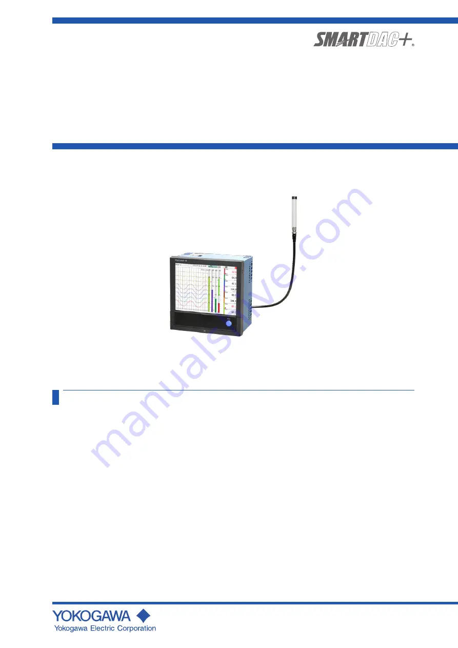
Model GX20W
Paperless Recorder
Wireless Model
User’s Manual
Contents
Introduction ................................................................................. 1
Checking the Package Contents ................................................. 3
GX20W Overview....................................................................... 4
Specifications ............................................................................. 4
Protection of Environment ........................................................... 7
External Dimensions and Panel Cut Dimensions.......................... 7
How to Connect with Wireless Field Equipment ........................... 9