Yoga 2-830F, Hardware Maintenance Manual
The Yoga 2-830F is a versatile and sleek tablet that is perfect for yoga enthusiasts on-the-go. For detailed instructions on hardware maintenance, download the free Manual from manualshive.com. Keep your device in optimal condition with the help of the comprehensive guide.
Share
Download


Reviews:
No comments
Related manuals for 2-830F

JTA-222
Brand: Jensen Pages: 8
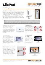
Armourdog LocPad ADLOC102W
Brand: Lente Designs Pages: 6

T.90 USB
Brand: Stanton Pages: 12

SOSPIRO-AS8W
Brand: Acer Pages: 15

Predator 8 GT-810
Brand: Acer Pages: 55

W510
Brand: Acer Pages: 90

DC22K
Brand: Acer Pages: 2

TD070VA1
Brand: Acer Pages: 79

Picasso
Brand: Acer Pages: 170

M44-7
Brand: Shure Pages: 4

B1-780
Brand: Acer Pages: 19

ellipsis 10
Brand: Verizon Pages: 12

DARK GLEE 10.1
Brand: SPC Pages: 29

9755116B
Brand: SPC Pages: 72

9.7 xenon
Brand: Archos Pages: 131

80 ChildPad
Brand: Archos Pages: 146

Challenger LP
Brand: auna Pages: 24

Classic Vintage Retro Style Turntable
Brand: Pyle Pages: 7


