background image

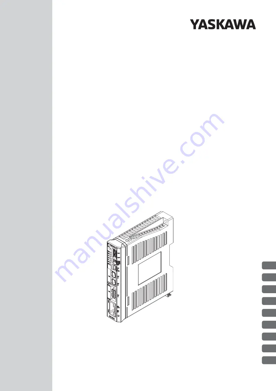
Model: JEPMC-GW3100-E

Gateway

MECHATROLINK-

III

 Compatible Device

Product Manual

MANUAL NO.   SIEP C880781 08B

1

2

3

4

5

6

7

8

9

Introduction to the GW3100

GW3100 Specifications

Interface Specifications

GW3100 Functions

Configuration Tool

Appendices

MECHATROLINK-

III

 Command Specifications

Part Names and

 Installation Methods

Operating Modes and

 Setting Methods

Summary of Contents for JEPMC-GW3100-E

Page 1: ...MANUAL NO SIEP C880781 08B 1 2 3 4 5 6 7 8 9 Introduction to the GW3100 GW3100 Specifications Interface Specifications GW3100 Functions Configuration Tool Appendices MECHATROLINK III Command Specific...

Page 2: ...liability is assumed with respect to the use of the informa tion contained herein Moreover because Yaskawa is constantly striving to improve its high quality products the information contained in this...

Page 3: ...his Manual Basic Terms Unless otherwise specified the following definitions are used Configuration Tool Used in this Manual In this manual screen captures of the M3M2 Gateway version 100 interface are...

Page 4: ...ecautions that will not result in machine damage Indicates items for which caution is required or precautions to prevent operating mis takes Indicates operating or setting examples Indicates supplemen...

Page 5: ...rked as shown below is important for safety Always read this information and heed the precautions that are pro vided DANGER Indicates precautions that if not heeded are likely to result in loss of lif...

Page 6: ...are subject to ambient humidity that exceeds the storage conditions Locations that are subject to rapid temperature changes and condensation Locations that are subject to corrosive or inflammable gas...

Page 7: ...risk of an accident Leave the specified amount of space between the Gateway Unit and other devices and between the interior surface of the control panel and other devices There is a risk of fire or ma...

Page 8: ...electrical shock injury or machine damage Do not change wiring while power is being supplied There is a risk of electrical shock injury or machine damage Dispose of the Gateway Unit as general industr...

Page 9: ...ed product in a manner in which it was not originally intended Causes that were not foreseeable with the scientific and technological understanding at the time of shipment from Yaskawa Events for whic...

Page 10: ...operty Systems that require a high degree of reliability such as systems that supply gas water or electricity or systems that operate continuously 24 hours a day Other systems that require a similar h...

Page 11: ...ns 1 6 1 3 3 Host Controller Conditions 1 6 Part Names and Installation Methods 2 2 1 Part Names and External Dimensions 2 2 2 1 1 Part Names 2 2 2 1 2 External Dimensions 2 3 2 1 3 Installation Space...

Page 12: ...n Layer Commands 4 5 4 3 USB Interface 4 6 4 3 1 Basic Specifications 4 6 GW3100 Functions 5 5 1 List of GW3100 Functions 5 2 5 2 Self Configuration 5 3 5 2 1 Execution with a Switch Setting and Turni...

Page 13: ...tallation Procedure 7 8 7 3 2 Disconnecting the Cable from a USB Connector 7 12 7 4 Operating the Configuration Tool 7 13 7 4 1 Starting the Configuration Tool 7 13 7 4 2 Main Window Details 7 14 MECH...

Page 14: ...Status n 0 to 3 8 26 8 6 6 Details in n Communications Status n 0 to 8 8 27 Appendices 9 9 1 Combinations of M II and M III Port Communications Settings 9 2 9 1 1 I O Gateway Mode 9 2 9 1 2 Transpare...

Page 15: ...e GW3100 1 2 1 1 2 GW3100 Features 1 3 1 2 Examples of GW3100 Applications and System Configuration 1 4 1 2 1 GW3100 Applications 1 4 1 2 2 System Configuration Example 1 5 1 3 Precautions 1 6 1 3 1 I...

Page 16: ...e GW3100 The GW3100 Gateway Unit functions as a gateway between a host controller level MECHA TROLINK III communications network and a MECHATROLINK II communications subnetwork All of the data exchang...

Page 17: ...ns There are two operating modes within this mode Stack Mode The M II command for the I O stations is stacked on the M III command without modification and sent to the GW3100 The host controller store...

Page 18: ...wing applications Increasing I O Capacity You can connect more than one I O station to one GW3100 station to increase the I O capacity of the station Complementing the M III Device Lineup You can use...

Page 19: ...DE CNFG CNFG INIT INIT ON ON 1 CN CN M M III III 2 2 CN CN 3 3 CN CN M M II II 4 4 MECHATROLINK ECHATROLINK POWER POWER DC DC 24V 24V DC DC 0V 0V GW3100 GW3100 X161 X160 YASKAWA SAVE RUN RUN ERR ERR L...

Page 20: ...ponse delays will occur when communicating through the Gateway Unit in comparison with a direct connection to an M III network Make sure that the command and response delays will not interfere with th...

Page 21: ...o make a 24 V power cable 2 1 Part Names and External Dimensions 2 2 2 1 1 Part Names 2 2 2 1 2 External Dimensions 2 3 2 1 3 Installation Space 2 3 2 2 Installation Methods 2 4 2 2 1 Mounting to a DI...

Page 22: ...icator Specifications on page 3 6 3 5 Connector Specifications on page 3 9 X161 X160 YASKAWA SAVE RUN RUN ERR ERR LK1 LK1 LK2 LK2 CN CN MTX MTX MER MER CN CN USB USB 1 1 ON SPARE SPARE MODE MODE CNFG...

Page 23: ...N CN 4 4 MECHATROLINK ECHATROLINK POWER POWER DC DC 24V 24V DC DC 0V 0V DC DC 24V 24V DC DC 0V 0V X1 X161 X1 X160 SPARE SPARE MODE MODE CNFG CNFG INIT INIT GW3100 GW3100 0 1 2 3 4 5 6 7 8 9 A BCD E F...

Page 24: ...e DIN rail mounting clip on the bottom of the GW3100 to release it 2 Hook the notch on the back of the GW3100 on the top of the DIN rail in the figure and then press the GW3100 toward the mounting sur...

Page 25: ...il 2 5 2 Part Names and Installation Methods This concludes mounting the GW3100 to a DIN rail as shown in the following figure Always install the GW3100 in an upright position After you install it mak...

Page 26: ...o screw holes located at the top and bottom at the back of the Unit Use two M4 screws in these holes to mount the GW3100 to a control panel Always install the GW3100 in an upright position After you i...

Page 27: ...handle included with the power plug or a screwdriver to loosen the power plug clamp and insert the conductors all the way to the back of the plug Using the Handle Hook the tip of the handle into a squ...

Page 28: ...eration Settings 3 4 3 3 2 Rotary Switches Address Setting 3 5 3 3 3 SAVE Switch Saving to Flash Memory 3 5 3 4 Indicator Specifications 3 6 3 5 Connector Specifications 3 9 3 5 1 MECHATROLINK III Con...

Page 29: ...ion 5 Hz to 8 4 Hz with single amplitude of 1 75 mm 8 4 Hz to 150 Hz with fixed acceleration of 4 9 m s2 Intermittent vibration 5 Hz to 8 4 Hz with single amplitude of 3 5 mm 8 4 Hz to 150 Hz with fix...

Page 30: ...tible Indicators Status indicators Refer to the following section for details 3 4 Indicator Specifications on page 3 6 Switches DIP switch Operation settings Rotary switches MECHATROLINK III station a...

Page 31: ...erter or Stepping Motor Drive OFF The operating mode is set accord ing to the devices connected to the M II port OFF I O Gateway Mode mode to connect I O devices CNFG ON Self configuration OFF If the...

Page 32: ...to Flash Memory This switch is used to save the parameter settings to flash memory Name Status Operation Default Remarks X161 0 to F Upper digit of station address 0 F cannot be used X160 0 to F Lower...

Page 33: ...he CN indicator lights only in I O Gateway Mode It will not light in Transparent Mode Indicator Color Status When Lit Remarks RUN Green GW3100 is operating ERR Red An error has occurred in the GW3100...

Page 34: ...as the result of pressing the SAVE switch It does not appear when data is saved to flash memory from the Configuration Tool Error A serious failure error occurred The watchdog timer shuts down the sys...

Page 35: ...ns are established with the M III network for all of the extended addresses that are being used A connection to the master was estab lished Connections are established with the M III network for only...

Page 36: ...ors are used to connect MECHATROLINK III communications devices Applicable MECHATROLINK Standard Cables 3 5 2 MECHATROLINK II Connector Specifications These connectors are used to connect MECHATROLINK...

Page 37: ...SB cable mini B type 3 5 4 Power Connector Specifications The power connector specifications are given below Connector Model Pin Assignments Name Connector Name No of Pins Connector Models Unit Side C...

Page 38: ...rface 4 2 4 1 1 Basic Specifications 4 2 4 1 2 Supported Commands 4 2 4 2 MECHATROLINK II Interface 4 5 4 2 1 Basic Specifications 4 5 4 2 2 Data Link Layer Commands 4 5 4 2 3 Application Layer Comman...

Page 39: ...e Slave only Slave Type Multi slave 4 stations max Supported Profile MECHATROLINK III standard profile Station Addresses 03 to EF hex Set on rotary switches Number of Transmission Bytes 16 32 48 or 64...

Page 40: ...Device 05 ALM_RD Read Alarm Warning 06 ALM_CLR Clear Alarm Warning 0D SYNC_SET Set Synchronization 0E CONNECT Establish Connection 0F DISCONNECT Release Connection 1B PPRM_RD Read Non volatile Parame...

Page 41: ...Phase 1 2 3 Servo Step ping Motor Drive Inverter Commands 00 NOP No Operation 01 PRM_RD Read Parameter 02 PRM_WR Write Parameter 05 ALM_RD Read Alarm Warning 1B PPRM_RD Read Non volatile Parameter 1C...

Page 42: ...4 2 3 Application Layer Commands The application layer commands depend on the operating mode I O Gateway Mode There are no application layer commands for simple I O The DATA_RWA application layer com...

Page 43: ...onous serial Transmission Method Half duplex Transfer Mode Controller transfers and bulk transfers Number of Connections USB host 1 Slaves 127 Including hubs Connector Type Series mini B plug Cable Le...

Page 44: ...2 1 Execution with a Switch Setting and Turning ON the Power Supply 5 3 5 2 2 Execution with the Configuration Tool 5 4 5 2 3 Operation Specifications for Self Configuration 5 4 5 3 M II M III Port S...

Page 45: ...nge the operating mode depending on the M II slaves that are connected and the application method Self Configuration The slave devices that are connected to the M II port are automatically detected an...

Page 46: ...itch setting and turning ON the power supply Execution with the Configuration Tool These methods are described below 5 2 1 Execution with a Switch Setting and Turning ON the Power Supply If you set th...

Page 47: ...s is exceeded eight stations for I O Gateway Mode and one station for Transparent Mode allocations are performed in order starting from the smallest station address Stations that exceed the maximum nu...

Page 48: ...I M III Port Synchronization The M II transmission cycle is synchronized to M III as long as the M II transmission cycle or M III transmission cycle is set to an integral multiple of the other This ma...

Page 49: ...u can use the Gateway Configuration Tool running on a host PC You connect the PC on which the Configuration Tool is installed to the PC with a USB cable The Configuration Tool provides the following f...

Page 50: ...meters 6 11 6 4 3 Saving to Flash Memory 6 15 6 4 4 Connecting the M II Slave Devices and Turning the Power Supply OFF and ON Again 6 15 6 5 Setting Parameters with the Configuration Tool 6 16 6 5 1 S...

Page 51: ...ters Maximum Number of Connectable M II Slave Stations 8 8 1 Minimum Value of M II Transmission Cycle Communications Cycle 500 s 500 s 500 s Asynchronous Operation of M II with M III Communications Cy...

Page 52: ...and the GW3100 The host controller stores the M II command in the M III command and the GW3100 separates the device commands for the M II slave stations and sends them to the stations The GW3100 takes...

Page 53: ...e 6 4 Response Data Flow in Stack Mode Master DATA_RWA RWDT Response 1 16 bytes Not used 12 bytes CMD_STAT Response 2 16 bytes Response 3 16 bytes Response 1 16 bytes Response 2 16 bytes Response 3 16...

Page 54: ...be used in this mode The flow of the command and response data in Pack Mode is illustrated in the following figures Command Data Flow in Pack Mode In this mode you can also set M II and M III communi...

Page 55: ...r I O 1 I O 2 I O 3 II M III M Gateway DATA_RWA RWDT 1 Simple I O Inputs 4 bytes Not used 22 bytes CMD_STAT 2 Simple I O Inputs 4 bytes 3 Intelligent I O 30 bytes Response 1 Response 2 Response 3 1 Si...

Page 56: ...d response data in Transparent Mode is illustrated in the following figures Command Data Flow in Transparent Mode If you connect a Servo Drive Stepping Motor Drive or Inverter you must set the same va...

Page 57: ...rent Mode POSING MONITOR1 STATUS ALARM MONITOR2 SEL_MON1 2 IO_MON RWDT SMON 0 SUBSTATUS SEL_MON3 4 MONITOR3 MONITOR4 POSING MONITOR1 STATUS ALARM MONITOR2 SEL_MON1 2 IO_MON RWDT SMON 0 SUBSTATUS SEL_M...

Page 58: ...number of M II slave sta tions node device types I O sizes etc 6 4 2 Setting the Gateway Parameters on page 6 11 Saving Data to Flash Memory Save the gateway parameter settings 6 4 3 Saving to Flash M...

Page 59: ...mode is set according to the devices con nected to the M II port OFF I O Gateway Mode mode to connect I O devices CNFG ON Self configuration If the CNFG pin is ON the slave connection status is automa...

Page 60: ...ded by the Configuration Tool You set the items and then click the Write Button to write the settings to the gateway parameters Refer to the following section for detailed setting procedures 6 5 Setti...

Page 61: ...2 1 Assigned Station 0 to 4 0 0303 2 1 Input Offset 0 to 63 0 0304 2 1 Input Data Size 0 to 31 0 0305 2 1 Output Offset 0 to 63 0 0306 2 1 Output Data Size 0 to 31 0 0400 2 2 Station Address 0 or 20...

Page 62: ...ut Offset 0 to 63 0 0704 2 5 Input Data Size 0 to 31 0 0705 2 5 Output Offset 0 to 63 0 0706 2 5 Output Data Size 0 to 31 0 0800 2 6 Station Address 0 or 20 hex or higher 0 0801 2 6 Type 0 No data ass...

Page 63: ...ata assigned 1 Intelligent I O 2 Simple I O 3 Servo Drive 4 Stepping Motor Drive 5 Inverter 0 0A02 2 8 Assigned Station 0 to 4 0 0A03 2 8 Input Offset 0 to 63 0 0A04 2 8 Input Data Size 0 to 31 0 0A05...

Page 64: ...ight again when the save operation is completed Execution with the Configuration Tool If you click the Flash write Button in the Configuration Tool the gateway parameter settings in the GW3100 will be...

Page 65: ...communications settings Transmission byte number of transmission bytes Determine the setting based on M II slave station specifications Transmission cycle and Number of retry to slaves number of slave...

Page 66: ...data is located as shown in the following diagrams for the above offset settings The input data is mapped in the same way Byte M III Command 0 DATA_RWA 1 WDC 1 Intelligent I O Adr 0x61 2 CMD_CTRL 3 By...

Page 67: ...and Number of retry to slaves number of slave station retries The values that you can set are determined by the number of transmission bytes and the number of connected nodes Select suitable values We...

Page 68: ...he above offset input and output settings The input data is mapped in the same way 1 Intelligent I O Adr 0x61 Byte M III Command Byte M II Command 0 DATA_RWA 0 DATA_RWA 1 WDC 1 OPTION 2 CMD_CTRL 2 3 3...

Page 69: ...nd Transmission byte number of transmission bytes There is always only 1 station The settings cannot be changed Transmission byte number of transmission bytes Determine the setting based on M II slave...

Page 70: ...owing methods to troubleshoot M II communications errors Indicators If an error occurs in communications between the M II slave station and the GW3100 the MER indicator will light Configuration Tool O...

Page 71: ...Installing and Uninstalling the Software 7 3 7 2 1 Installation 7 3 7 2 2 Uninstallation 7 7 7 3 Installing the USB Communications Driver 7 8 7 3 1 USB Communications Driver Installation Procedure 7...

Page 72: ...stall the Configuration Tool on a computer To connect a computer to the GW3100 with USB you must install the USB communications driver on the computer in advance Refer to the following section for the...

Page 73: ...following icon which is created when you downloaded the Configura tion Tool to your computer The Installer will be extracted and the following Setup Icon will be displayed 2 Double click the Setup Ic...

Page 74: ...on 7 4 5 Read the agreement and then select the I accept the terms of the license agreement Option Then click the Next Button The Customer Information Dialog Box will be displayed 6 Enter the followin...

Page 75: ...ion 7 5 7 Configuration Tool 7 Specify the destination folder To change the destination folder Click the Browse Button and select the desired destination by fol lowing the guidance displayed in the di...

Page 76: ...7 2 Installing and Uninstalling the Software 7 2 1 Installation 7 6 10 Click the Finish Button This concludes the procedure to install the Configuration Tool on your computer...

Page 77: ...re to uninstall the software 1 Select Control Panel from the Windows Start Menu and then select Programs 2 The Uninstall or Change a Program Dialog Box will be displayed Select M3M2 Gateway and then c...

Page 78: ...the USB communications driver 1 Connect the USB port on the GW3100 to a USB port on your computer with a USB cable mini B series and then turn ON the power supply to the GW3100 Note Some time may be r...

Page 79: ...ommunications Driver 7 3 1 USB Communications Driver Installation Procedure 7 9 7 Configuration Tool 5 Click Browse my computer for driver software 6 Click the Browse Button The Browse For Folder Dial...

Page 80: ...3M2 Gateway Folder and then click the OK Button There are different USB communications driver folders for different operating systems as shown below Win7 86 Driver for Windows 7 or Windows 8 32 bit ed...

Page 81: ...3 1 USB Communications Driver Installation Procedure 7 11 7 Configuration Tool 10 Make sure that MP Series USB Device is displayed under Universal Serial Bus control lers This concludes the installati...

Page 82: ...while USB is connected 1 Click the Eject GW3100 USB IF Icon in the Task Tray at the lower right of your screen A popup menu containing Safe To Remove Hardware will be displayed 2 Select this menu comm...

Page 83: ...ibes the Main Window in detail 7 4 1 Starting the Configuration Tool Use the following procedure to start the Configuration Tool 1 Perform any of the following operations Double click the Configuratio...

Page 84: ...e Saves the project file Gateway USB Adr Sets the USB address to which to connect 1 to 127 Read Reads project information from the GW3100 Write Writes project information to the GW3100 FLASH write Sav...

Page 85: ...2 Transmission cycle Set the transmission cycle 0 5 1 1 5 2 3 or 4 Number of retry to slaves number of slave station retries Select the number of slave station retries 0 to 7 Number of slaves number o...

Page 86: ...pported 8 3 8 1 6 Establish Connection Command CONNECT 0E Hex 8 3 8 1 7 Read Non volatile Parameter Command PPRM_RD 1B Hex 8 4 8 1 8 Write Non volatile Parameter Command PPRM_WR 1C Hex Not Currently S...

Page 87: ...5 8 6 1 Details in the Version Information 8 25 8 6 2 Details in Operation Settings 8 25 8 6 3 Details in Run Status 8 25 8 6 4 Alarm Details 8 26 8 6 5 Details in Extended Address n Communications St...

Page 88: ...and the meanings of the ID codes 8 3 ID_CODE List on page 8 13 8 1 4 Setup Device Command CONFIG 04 Hex Command Parameter CONFIG_MOD Configuration Mode 0 Set up 1 Save parameters to flash memory 8 1 5...

Page 89: ...ed The GW3100 does not currently support this command If you use it CMD_ALM will be set to 8 unsupported command received 8 1 9 Read Memory Command MEM_RD 1D Hex Not Currently Supported The GW3100 doe...

Page 90: ...3 3 4 Command data 4 Response data 5 5 30 30 31 31 Command Code Setting Range Setting Unit Byte 0 20 hex Description Command code for standard I O profile commands DATA_RWA 20 hex Asynchronous Data Re...

Page 91: ...es 2 and 3 Description Command Status for Standard I O Profile Commands Bit 0 D_ALM 0 Normal 1 Device alarm Bit 1 D_WAR 0 Normal 1 Device warning Bit 2 CMDRDY 0 Command reception not possible 1 Ready...

Page 92: ...d when the CONNECT command was received did not agree with the operating mode Check the communi cations settings in the master station Possible E60 hex reception error 9 0 A reception error occurred t...

Page 93: ...he PRM_RD or PRM_WR command is out of range Check the com mand data that was sent by the control ler Automati cally cleared 94B hex data out of range 0 9 The command data in a command other than an ID...

Page 94: ...III command is used as a buffer memory for the host computer to set the M II command data The location of the M II command data depends on a parameter setting The data for more than one station is sto...

Page 95: ...set the M II response data The location of the M II response data depends on a parameter setting In the same way as for commands the response for more than one station can be stored Byte M III Respon...

Page 96: ...ces where the host computer sets the command data The location of the command data depends on a parameter setting The data for more than one station can be set Intelligent I O Byte M II Command Byte M...

Page 97: ...for more than one station can be stored 8 2 2 Synchronous Data Read Write Command DATA_RWS 21 Hex The GW3100 does not currently support this command If you use it CMD_ALM will be set to 8 unsupported...

Page 98: ...t the device supports The value depends on a setting on the DIP switch I O Gateway Mode Returns 30 hex Transparent Mode Returns 00 hex 11 Profile Version 1 Primary 00000100 hex 4 bytes Binary data Yes...

Page 99: ...s All 8 bytes are 00 hex 8 bytes Binary data Description Not used by the GW3100 All zeros will be read 30 List of Supported Main Commands Standard I O profile 0800C07F hex 00000003 hex 00000000 hex 00...

Page 100: ...0 Reserved 0 HOLD SENS_OFF SENS_ON BRK_OFF BRK_ON POS_SET 0 0 1 1 1 1 1 1 Bit 47 Bit 46 Bit 45 Bit 44 Bit 43 Bit 42 Bit 41 Bit 40 Reserved 0 Reserved 0 Reserved 0 Reserved 0 Reserved 0 Reserved 0 LTM...

Page 101: ...he GW3100 All zeros will be read Continued on next page Continued from previous page ID_CODE Hex Contents Value Data Size Data Type Supported Bit16 to Bit23 Reserved for system 0 Bits 32 to 39 Reserve...

Page 102: ...evice 3 Name All 32 bytes are 00 hex 32 bytes ASCII delimiter 00 Not sup ported Description Not used by the GW3100 All zeros will be read B8 Sub Device 3 Version 00000000 hex 4 bytes Binary data Not s...

Page 103: ...000C Reserved for system 0 8000 002C 1 Output Data Size 8000 000D 8000 002D 8000 000E Reserved for system 0 8000 002E Reserved for system 0 8000 000F 8000 002F 8000 0010 Baud Rate 8000 0030 2 Station...

Page 104: ...0085 8000 0056 4 Input Offset 8000 0086 7 Input Offset 8000 0057 8000 0087 8000 0058 4 Input Data Size 8000 0088 7 Input Data Size 8000 0059 8000 0089 8000 005A 4 Output Offset 8000 008A 7 Output Offs...

Page 105: ...served for system 0 8000 00E6 8000 00B7 8000 00E7 8000 00B8 Model number J 8000 00E8 Extended Address 0 Communications Status 8000 00B9 E 8000 00E9 8000 00BA P 8000 00EA Extended Address 1 Communicati...

Page 106: ...18 0019 2 Number of Slave Sta tion Retries 0 to 7 0 0205 001A 001B 2 Number of Connected Nodes 0 to 8 0 0300 0020 0021 2 1 Station Address 0 or 20 hex or higher 0 0301 0022 0023 2 1 Type 0 No data ass...

Page 107: ...e 0 No data assigned 1 Intelligent I O 2 Simple I O 3 Servo Drive 4 Stepping Motor Drive 5 Inverter 0 0702 0064 0065 2 5 Assigned Station 0 to 4 0 0703 0066 0067 2 5 Input Offset 0 to 63 0 0704 0068 0...

Page 108: ...in the Version Information on page 8 25 Read only 0D02 00DC 00DD 2 Operation Settings Reports the setting of pin 1 on the DIP switch Refer to the following section for details 8 6 2 Details in Operat...

Page 109: ...3 2 2 Communications Status 0F02 00F4 00F5 2 3 Communications Status 0F03 00F6 00F7 2 4 Communications Status 0F04 00F8 00F9 2 5 Communications Status 0F05 00FA 00FB 2 6 Communications Status 0F06 00F...

Page 110: ...23 Bit 16 Bit 15 Bit 8 Bit 7 Bit 0 Major version BCD 00 to 99 Minor version BCD 00 to 99 Sample version BCD 00 Not used Always 0 Bit Name Meaning 0 SPARE Reserved for system 1 MODE 0 I O Gateway Mode...

Page 111: ...system Bit Name Meaning 0 D_ALM 0 Normal 1 Device alarm 1 D_WAR 0 Normal 1 Device warning 2 CMDRDY 0 Commands cannot be received 1 Ready to receive commands 3 ALM_CLR_CMP 0 ALM_CLR execution not compl...

Page 112: ...nd Specifications 8 6 6 Details in n Communications Status n 0 to 8 The bit details in the n communications status are as follows Bit Name Meaning 0 D_ALM 0 Normal 1 Alarm 1 D_WAR 0 Normal 1 Warning 2...

Page 113: ...2 Transparent Mode 9 3 9 2 Throughput 9 4 9 2 1 Throughput for I O Gateway Mode 9 4 9 2 2 Throughput for Transparent Mode 9 5 9 3 Using the Gateway Unit with MP2000 and MP3000 Series Machine Controll...

Page 114: ...tions cycle must be the same as the transmis sion cycle 1 x transmission cycle You can set the communications cycle of the M III port in I O Gateway Mode to any value that is an integral multiple of t...

Page 115: ...ansparent Mode must be set to the same value as the M II port communications cycle The following table shows the possible combinations of the M II port and M III port transmis sion cycles in Transpare...

Page 116: ...e M III transmission cycle 2 M II transmission cycle 2 Response Time Response time M III transmission cycle 2 M II transmission cycle 2 Command M III transmission cycle M III slave transmissions M III...

Page 117: ...ponse time M III transmission cycle 3 Command M III transmission cycle M III slave transmissions M III master transmissions M II slave transmissions M II master transmissions Command M II transmission...

Page 118: ...supported Name Model Operating Mode I O Gateway Mode Transparent Mode MP3100 16 axes JAPMC MC3100 1 E Supported Not supported MP3100 32 axes JAPMC MC3100 2 E Supported Not supported CPU 201 JEPMC CP32...

Page 119: ...et the operating mode Turn OFF the CNFG pin on the DIP switch 6 4 1 Switch Settings on page 6 10 Switch Settings Set the operating mode and M III slave address Turn OFF the CNFG pin on the DIP switch...

Page 120: ...he M II device and the Gateway Unit Machine Controller Switch Setting Turn ON the CNFG pin on the DIP switch Turning the Machine Controller Power Supply ON Execute self configuration Start communicati...

Page 121: ...in run status 8 25 details in the version information 8 25 details on common commands 8 3 details on standard I O profile commands 8 5 DIN rail 2 4 DIN rail mounting clip 2 2 2 4 DIP switch 2 2 3 4 se...

Page 122: ...ler 9 7 SPARE 3 4 Stack Mode 6 2 6 3 setting parameters 6 16 Start Synchronous Communications command 8 3 status indicators 2 2 3 6 combined meaning 3 7 supported commands 4 2 M II compatible profile...

Page 123: ...te of Publication Rev No Web Rev No Section Revised Contents March 2022 1 2 1 2 2 Partly revised Back cover Revision Address May 2020 1 3 5 1 3 5 2 Partly revised December 2019 0 Front cover and back...

Page 124: ...w yaskawa co th YASKAWA ELECTRIC CHINA CO LTD 22F Link Square 1 No 222 Hubin Road Shanghai 200021 China Phone 86 21 5385 2200 Fax 86 21 5385 3299 www yaskawa com cn YASKAWA ELECTRIC CHINA CO LTD BEIJI...

Reviews: