background image

YY-36xx Series Instruction Manual 


Safety Information Reminder: 

* Power off and unplugging the power cord before accessing the chassis.     
**Many products use parts that are known to be sensitive to electric Static Discharge (ESD), to prevent damage when 
you work with ESD-sensitive parts. 
***Make sure there are no loose parts/screws inside the chassis, when complete the assembly. 

   
Please find all necessary parts from accessory bag, and follow steps below for system assembly. 
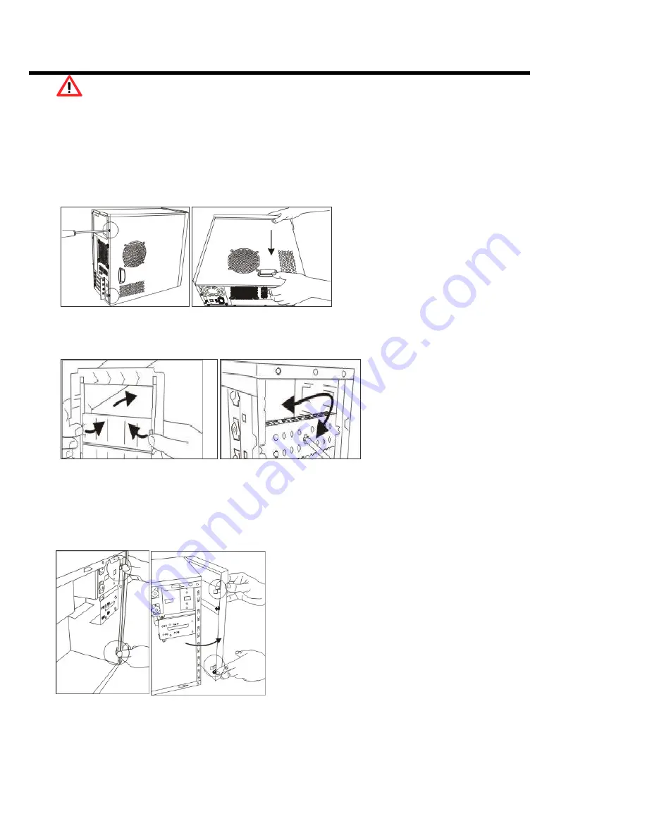
 

1. Opening Chassis


Release screws on the back of chassis. 


Push the cover toward the rear chassis, should stop 

about moving 1/2 inch, than the side cover could be 

lift up. 


2. When will need to remove the front panel   

2.1. When user wants to install more 

5.25”/3.5”devices – must remove the plastic 

dummy covers from the front panel, and the 

EMI shielding metal covers from the front of 

chassis as arrows shown. The removed EMI 

shielding covers could be re-used by screws. 


2.2. When user wants to install a cooling fan in the front of chassis (please refer item 9, 9-2) 

2.3. When user wants to install an optional 3.5”cage for more HDD installation (please refer item 5, 5.2.) 


3. How to remove the front panel 

After removing the side cover.   

Push hooks marked in circle to detach the front panel from the 

chassis. 


Do not try to swing or pull straightly out; the hooks of front 

panel may be damaged. 


Summary of Contents for YY-36 series

Page 1: ...op about moving 1 2 inch than the side cover could be lift up 2 When will need to remove the front panel 2 1 When user wants to install more 5 25 3 5 devices must remove the plastic dummy covers from the front panel and the EMI shielding metal covers from the front of chassis as arrows shown The removed EMI shielding covers could be re used by screws 2 2 When user wants to install a cooling fan in...

Page 2: ...hield provided with mainboard insert it from inside of chassis towards outside Screw off the PCI holder bracket in the rear end of chassis remove the bracket Insert add on card into slot The bracket is designed to fix all add on cards in one screw 5 Installing 3 5 devices 5 1 Remove the screw marked in circle Pull the 3 5 cage toward the rear chassis Screw on the card reader or FDD with M3 type sc...

Page 3: ...he fastener as marked direction Insert the 5 25 device into the 5 25 drive bay until in correct position hole to hole Depress the fastener tightly There are some 5 25 devices with shorter depth i e the fan controller probably is not able to be fixed by the fastener User still may screw it onto the circled mounting holes 7 Cables mounting FPIO connectors The pin out of USB2 0 AUDIO iEEE1394 header ...

Page 4: ...with cooling fan to screw on from back towards front 9 2 Another alternative fan position is located in the front of chassis user must remove the front panel when screw on the cooling fan Suggestion The chassis is compliant with Thermally Advantaged Chassis design guide the side cover is attached an air guide which is helpful to brow in cool air for processor area A system cooling fan installed in...

Reviews: