Yamaha QT 50F, Service Manual
Introducing the Yamaha QT 50F - a compact and versatile scooter designed for convenience and efficiency. Ensure its optimal performance with our comprehensive Service Manual, available for free download at manualshive.com. This invaluable manual provides step-by-step instructions to maintain and troubleshoot your Yamaha QT 50F, guaranteeing a smooth and hassle-free ride.
Share
Download


Reviews:
No comments
Related manuals for QT 50F

Century
Brand: LAZER Pages: 6

1980 CB900C
Brand: Honda Pages: 393

B902L
Brand: N-Com Pages: 36

IGNITE 509
Brand: Dennis Kirk Pages: 5

160 STREET
Brand: Avenger Pages: 31

GS500E
Brand: Suzuki Pages: 440

650949 01 01
Brand: hepco & becker Pages: 2
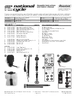
Quantum hardcoated N30214-WK
Brand: National Cycle Pages: 13

CoreManual TorqDrive
Brand: Rekluse Pages: 20

F9903S6
Brand: KTM Pages: 26

Superbike 749R 2006
Brand: Ducati Pages: 608

XV250M1 2020
Brand: Yamaha Pages: 98

Star XVS13CB(C)
Brand: Yamaha Pages: 100

XV19CSA
Brand: Yamaha Pages: 96

XV19SW 2006
Brand: Yamaha Pages: 145

ROADLINER XV19SW
Brand: Yamaha Pages: 444

XV19SX(C)
Brand: Yamaha Pages: 494

XVS1100V
Brand: Yamaha Pages: 94


