background image

COLOR TELEVISION

LC

3

0

B1

Summary of Contents for LC30B1

Page 1: ...COLOR TELEVISION LC30B1 ...

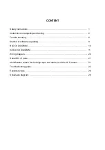
Page 2: ...uble shooting Method of software upgrading BLOCK DIAGRAM IC BLOCK DIAGRAM Wiring diagram Serial NO of parts Identification criteria for the bright spot and dark spot of the LCD screen Troubleshooting guide Exploded views Schematic diagram 1 2 6 8 10 11 20 21 21 22 26 28 ...

Page 3: ...or nearby fire source heating equipment and devices or exposure to sunlight etc Otherwise bad effect will result 2 5 If any foreign substance such as water liquid metal slices or other matters happens to fall into the module be sure to cut the power off immediately and do not move anything on the module lest it should cause fire or electric shock due to contact with the high voltage or short circu...

Page 4: ...tent of the residual picture varies with the maker of LCD screen This phenonmenon doesn t represent failure This ghost shadow may remain in the picture for a period of time several minutes But when operating it please avoid displaying still picture in high brightness for a long time 3 Points for attention during installation 3 1 The front panel of LCD screen is of glass Wheng installing it please ...

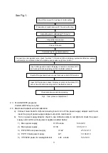
Page 5: ... terminal L24 anode 5 V 0 2 V Check if memory U16 has been FLASH written Production of main board and TV board on the line Check the main board Check TV board Combined test for general assembly Connect to central signal source check if various TV functions station skipping system identification analog control etc are normal and check if earphone and speaker output are normal Input AV S signal and ...

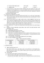
Page 6: ...y to access the ex works preset channel and check if the screen display is normal 2 6 Adjustment of white balance Use white balance meter CA210 and signal generator K7253 specialized for LCD 2 6 1 Assemble the complete set 2 6 2 Press signal source key to enter YpbPr 2 6 3 Input signal YPbPr 640x480p 60 Hz K7253 2 6 4 Enter user menu and set the brightness to 50 and contrast to 50 Press factory ke...

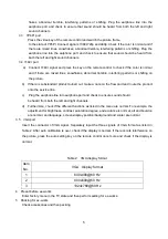
Page 7: ...ned out make a note on the flow card and route the product onto the service line c Plug the earphone line into earphone port and check to ensure sound should be heard from both the left and right channels d Furthermore check if the different functions as listed in the menu are normal For example the adjustment for brightness contrast saturation degree and acutance is normal alt and bourdon are nor...

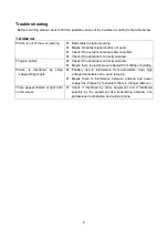
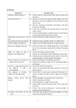
Page 8: ...tenna is correctly oriented Maybe there is electric wave reflected from hilltop or building Picture is interfered by stripe shaped bright spots Possibly due to interference from automobile train high voltage transmission line neon lamp etc Maybe there is interference between antenna and power supply line Please try to separate them in a longer distance There appear streaks or light color on the sc...

Page 9: ...he liquid crystal TV set and make proper adjustment according to the signal types Picture too bright and there is distortion in the brightest area Check if the contrast setting is too high Possibly the output quality of DVD broadcaster is set too high It maybe also due to improper terminal connection of the video frequency signal in a certain position of the system Picture is whitish or too bright...

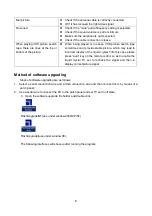
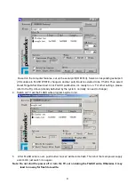
Page 10: ...h may lead to incorrect display of the liquid crystal TVIn this case please press auto key on the remote control so as to enable the liquid crystal TV set to recheck the signal and then to display correct picture signal Method of software upgrading Steps of software upgrading are as follows 1 Select a serial connection wire and a VGA connection wire and then connect them by means of a patch panel ...

Page 11: ... it s ready to run For other settings please refer to the Fig Above already defaulted by the system normally no need to change 4 Switch on TV set the FLASH write program begins to run 5 After FLASH write is over push button cancel will become flash Then shut the main power supply and it s OK just switch it on again Note Do not shut the power off or turn the TV set on during the FLASH write Otherwi...

Page 12: ......

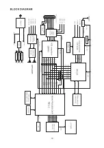
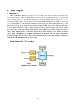
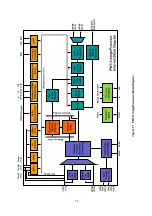
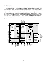
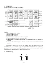
Page 13: ... and D HS line synchronizing D VS field synchronizing DCLK 82 MHz clock signal and D EN enable signal The external control signal received by PW113 includes IRIN of Pin203 signal received by remote control KEY 2 7 of PORTA push key control signal and reset signal etc Major control signals output from PW113 include backlight control signal BKLON Pin 40 Panel power supply control signal LCDON Pin 39...

Page 14: ...12 ...

Page 15: ...used to adjust the brightness and contrast of the channel Nevertheless the brightness and contrast adjustment function of this TV set is performed by regulating the front end VPC3230 After the digital video signal received by PW1230 from VPC3230 is deinterlaced it is output as 24bit digital RGB signal to GPORT of N15 PW113 where it is processed The output signals as DDCK CLOCK DDVS FIELD SYNCHRONI...

Page 16: ... of 20 25MHz and supply local frequency to VPC3230 Pins 13 14 are SAF AND SCL signals for bus line 12 to be used for communication with MCU PW113 VPC3230 that is used as video decoding chip sends the digital video signal in the format of CCIR601 which is decoded from the analog video signal CVBS S VIDEO YCBCR to the deinterlacing processor N11 PW1230 where conversion is made from interlace to non ...

Page 17: ...rol pin for MUTE valid when it is of high electric level Pin 13 is power supply pin for IC 24V Pins 12 14 are for power amplification output output electric level is 10V For TDA7495 only when two control pins 9 and 10 are valid at the same time can there be sound output When servicing with power on please take care not to short circuit the IC pin or the power supply because IC is liable to burnout...

Page 18: ...has four pairs of audio input ports which are respectively TV PC AUDIO HD R HD L AV R AV L The four groups of inputs connected through bus line 12 to PW113 which control the audio signal corresponding to the output according to different SOURCES 8 AD9883 N6 ...

Page 19: ...17 9 K4S641632C N12 10 DS90C383A N16 D S 90C 383A D S 90C F383A ...

Page 20: ...18 11 Z86129 N8 ...

Page 21: ...19 12 LVC16244 N13 N14 13 PI5330 N1 14 74LV126 N4 ...

Page 22: ......

Page 23: ... It is identified as a defected point if its area exceeds 1 2 of a single picture element R G B 2 Definition of bright spot It is identified as a bright spot if it is bright in the state of dark field and its bright size remains unchanged 3 Definition of dark spot It is identified as a dark spot if it is dark in the state of white field and its dark size remains unchanged 4 Definition of two neigh...

Page 24: ...er light Replace adapter Check whether N25 Pin 7 is high level Replace N25 test X17 pin 1 and 2 and check whether the voltage is 12V and 24V Check whether N17 pin 5 the voltage 12V Replace N17 Check X21 pin 9 10 11 12 16 17 1 8 19 20waveform Replace PANEL Replace signal processing board ...

Page 25: ... and YPBPR no picture yes no no yes yes no no no Check N1 pin 12 waveform Replace N1 PI5V330 Check R21 R131 pin waveform Replace N6 AD9883 Check R89 pin waveform Replace N15 PW113 Replace N16 DS90C383A Check N15 pin 170 waveform Replace G2 ...

Page 26: ...yes yes no no yes Check R55 R56 R57 pin waveform Check N11 pin62 waveform Replace G1 Replace N10 Check R64 R65 R66 pin waveform Check R82 R89 R93 pin waveform Replace N16 Check N15 pin170 waveform Replace N15 Replace G2 Check N16 pin40 waveform Replace G3 Replace N11 ...

Page 27: ...es yes yes no Check X4 pin2 waveform Replace TV board Check fault 2 Check X601 pin 1 and 3 waveform Check whether U601 pin13 the voltage 24V Replace U26 Replace TV board Check U5 pin 24 and 25 waveform Check adapter power Replace sound amplifer board ...

Page 28: ...26 EXPLODED VIEWS 1 2 3 4 5 6 7 8 9 10 11 12 13 14 15 16 17 18 19 ...

Page 29: ...ew 3 Sound leading part 13 back cover board 4 Speaker s back cover 14 screw 5 Speaker connector 15 parts of keys 6 Front cabinet 16 back cabinet 7 LCD screen connecting frame 17 Fixing frame 8 LED column 18 main board 9 LCD panel 19 main board frame 10 Signal cable supporter ...

Page 30: ......

Page 31: ......

Page 32: ......

Page 33: ......

Page 34: ......

Page 35: ......

Page 36: ......

Page 37: ...V 1 9V 5V 1 5V 1 5V 1 L506 10uH C80 16V 10u C81 0 1u C82 470p C70 1n C71 1n C72 1n C73 1n C74 1n C62 10u C61 10u C88 470p C87 0 1u C86 10u L504 10uH C75 10u C76 0 1u C78 0 1u C77 4 7u C85 470p C84 0 1u C83 10u LB 10uH C52 56p Z1 18 432M C63 33p C64 33p J10 PC AUDIO C60 0 33u C59 0 33u C58 0 33u C57 0 33u C56 0 33u C55 0 33u R505 10K R506 10K R504 10K R503 10K R502 10K R501 10K 1 2 3 4 5 6 7 8 VCC ...

Page 38: ...u C606 25V 470u V601 RN1204 V602 RN1204 R604 10K R605 10K 5V 5V C611 35V 470u C615 35V 470u X603 X602 C614 0 1u C616 25V 1000u L603 75uH VD604 RGP10 R608 1 4W 3 6K D602 5Z1 C609 0 1u C613 25V 47u 5V R609 10K R610 10K VD603 IN4148 V603 2SC1015 C610 25V 47u R607 10K 1 1 R606 3 3K VD601 5Z1 IN_R IN_L STBY MUTE L_OUT R_OUT 1 AUDIO X601 J11 0 J9 空 J1 空 J4 0 C607 25V 1u C608 25V 1u L602 10uH L601 10uH C...

Reviews: