xG Technology CN1100, Installation Manual
The xG Technology CN1100 comes with a comprehensive Installation Manual, available for free download from manualshive.com. This manual provides detailed instructions on setting up and using the CN1100, ensuring a smooth and hassle-free installation process. Get your manual today and maximize the performance of your device.
Share
Download


Reviews:
No comments
Related manuals for CN1100

Rangebooster N 650 Access Point DAP-1353
Brand: D-Link Pages: 67

DWL-1000AP
Brand: D-Link Pages: 8
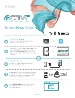
COVR-2202
Brand: D-Link Pages: 2

DAP-1155
Brand: D-Link Pages: 3

Air Premier DAP-2695
Brand: D-Link Pages: 39
AirPlus DI-714P+
Brand: D-Link Pages: 5
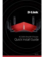
AC5300
Brand: D-Link Pages: 12
SharePort DIR-825
Brand: D-Link Pages: 20
Express EtherNetwork DI-604
Brand: D-Link Pages: 49

E400
Brand: Cambium Networks Pages: 5

E400
Brand: Cambium Networks Pages: 44

WA2200 Series
Brand: H3C Pages: 42

NF12
Brand: NetComm Pages: 3

EW-7203APg
Brand: Edimax Pages: 2

BLUESOCKET 1930
Brand: ADTRAN Pages: 4

NBG-415
Brand: ZyXEL Communications Pages: 109

ZSR0104UP
Brand: Zonet Pages: 51

T073G HGU ONT
Brand: Calix Pages: 20


