


Reviews:
No comments
Related manuals for Apollo-X7

3
Brand: YELLOWBRICK Pages: 2

Triton 300
Brand: Magellan Pages: 2

eXplorist 600
Brand: Magellan Pages: 123

Ubitag V2.2
Brand: Ubisense Pages: 7

VT04
Brand: Spectrum Pages: 9

Hero 350x
Brand: Sureshotgps Pages: 13
GV4300
Brand: Prestigio Pages: 42

ES825
Brand: eSky wireless Pages: 18

NA-4010
Brand: Naxa Pages: 17

NT08E
Brand: Kingwo Pages: 22

Kompy Pico
Brand: SafetyTracer Pages: 6

Compasseo 600
Brand: Packard Bell Pages: 18

NT-V4
Brand: US Fleet Tracking Pages: 2

BT4
Brand: B.O.L.T Pages: 51

Tag-It
Brand: TZUMI Pages: 6
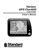
GPS Chart400
Brand: Standard Communications Pages: 34

P-3600
Brand: Caliber Pages: 98
Quicksilver GPS
Brand: Icom Pages: 2


