background image

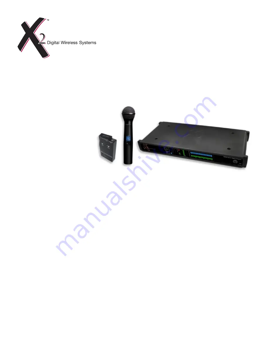
Digital UHF Wireless System
Model XDR-95

x

Users Guide

Includes easy setup instructions for single and multi-system operation

24-bit Digital Conversion 
No Companders
Frequency Diversity (anti-jam) Technology
Extended Operating Range
Reliable, Wired Sound and Performance
Multi-channel Operation

X2 Digital Wireless Systems

4630 Beloit Drive, Suite 20

Sacramento CA 95838 U.S.A.

Phone: (916) 779-1040

Fax: (916) 779-1041

Web Site

www.x2digitalwireless.com

Summary of Contents for XDR-95x

Page 1: ...ion 24 bit Digital Conversion No Companders Frequency Diversity anti jam Technology Extended Operating Range Reliable Wired Sound and Performance Multi channel Operation X2 Digital Wireless Systems 46...

Page 2: ...on 7 Operation Assigning the Transmitter a Name 7 Operation Selecting Mute Mode 7 Preparing the Handheld Transmitter for Use 8 Battery Installation 8 Bodypack Transmitter Controls 9 Changing Transmitt...

Page 3: ...antenna to the BNC connectors on the back panel of the receiver And for even greater flexibility the sys tem ships complete with a front mount antenna kit that allows you to bring the BNC connectors a...

Page 4: ...1 front mount antenna kit includes necessary hardware see front mount antenna installation instructions on page 5 1 Handheld Systems Include 1 XDH4 digital handheld transmitter 1 Microphone capsule 1...

Page 5: ...etry will be disabled when using XDT1 transmitters Changing Modes To change the operating mode power the unit off press and hold the Channel DOWN button and power up The unit will remain in the newly...

Page 6: ...ble into the CABLE GRIP to secure the connection as shown in figure 3 FIGURE 3 DC Power Input DC socket for connection of power supply 9V DC 500 mA supplied Instrument Output Jack This 1 4 unbalanced...

Page 7: ...NOT DC biased FIGURE 4 Preparing Rack Ears for Installation Connect the supplied BNC connector to each rack ear prior to installing the rack ears to the chassis Make certain that the nut goes on the b...

Page 8: ...lockwise for 1 2 turn then connect the other end to the BNC connector located on the back side of each rack ear and twist cloclwise for 1 2 turn Finally connect the 1 2 wave antenna by pressing on the...

Page 9: ...on to put the transmitter in different modes of operation accept selected values or to exit without making any changes Select Button This is used for controlling the LCD interface Use this button to m...

Page 10: ...it is returned back to standard operation Should the transmitter be left in this state until the batteries expire simply replace the batteries and press the power button The transmitter will power up...

Page 11: ...ttery Installation Remove battery cover by turning counter clockwise and pulling down Install the two supplied AA alkaline batteries observing correct polarity Then close the battery compartment by tu...

Page 12: ...range and can accommodate input signals up to 6V peak to peak Operating Modes for the Transmitter The XDT4 ships in XDS mode from the factory and ensures that your system is operating at full bandwid...

Page 13: ...ating Mode To change the operating mode power the unit off press and hold the Channel DOWN button left button and power up The unit will remain in the newly chosen and displayed mode until you repeat...

Page 14: ...nput Jack Socket Make certain that a secure connection is made for trouble free operation Instrument Input The instrument input circuit is wired to the ring of the input jack plug and socket NOTE When...

Page 15: ...should last about 5 5 hours in the XDT4 NiCad rechargeable batteries will only last about 3 5 hours Standard batteries are not recommended THE BATTERY HOUR DISPLAY WILL ONLY BE ACCURATE FOR ALKALINE B...

Page 16: ...achable so that you can also attach the bodypack transmitter with the input jack facing downwards To do so remove the clip and remount it reversing the orientation as shown in figure 17 For thinner ny...

Page 17: ...e battery status indicator on the transmitter and replace if necessary Signal Source Make certain that the source is operating as desired by checking source power signal levels and connections If nece...

Page 18: ...d maximum performance range There should be a free line of sight between transmitters and receiving antennas For best results maintain a line of sight between transmitter and receiver antennas Move re...

Page 19: ...s for a Class B digital device pursuant to part 15 of the FCC Rules These limits are designed to provide reasonable protection against harmful interference in a residential installation This equip men...

Page 20: ...rt If the problem persists call X2 at 916 779 1040 and request the customer service department Talk your situation over with one of our technicians if necessary you will be given a return authorizatio...

Page 21: ...trols Power On RF Channel Diversity Battery Life Audio Level Meter Power On Off Channel UP and Down Dimensions HxWxD 1 44 x 4 5 x 5 65 in 3 66 x 11 43 x 14 35 cm Power Requirements 9V DC 300mA via inc...

Page 22: ...terference including DTV cell phones blackberrys and networking devices XDR95 was designed to address the needs of professional wireless users requiring consistent reliable performance even in adverse...

Page 23: ...X2 Digital Wireless Systems 4630 Beloit Drive Suite 20 Sacramento CA 95838 U S A Phone 916 779 1040 Fax 916 779 1041 Web Site www x2digitalwireless com Friday January 11 2008...

Reviews: