background image

OWNER'S MANUAL

(FOR MODELS MANUFACTURED SINCE 02/19)

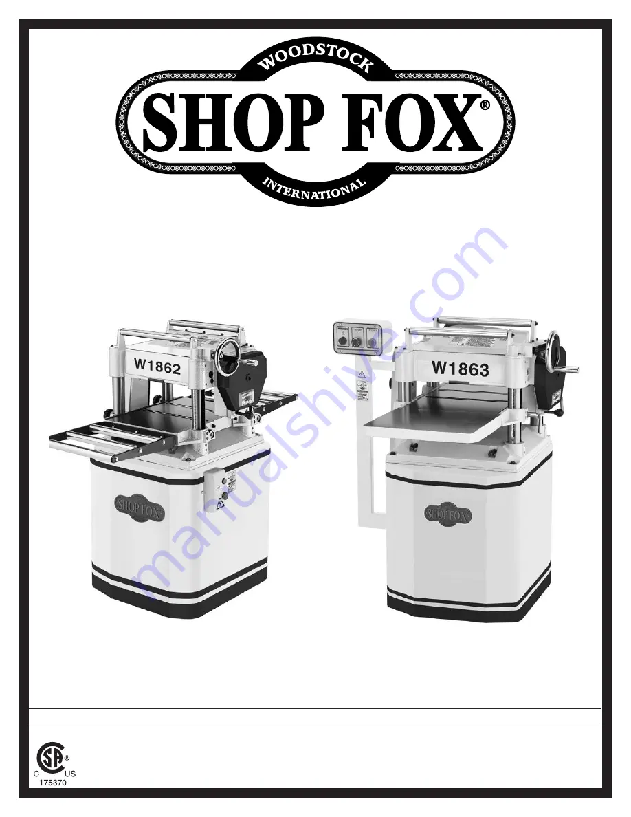
MODEL W1862/W1863

15" PLANERS

Phone: (360) 734-3482 • Online Technical Support: [email protected]

COPYRIGHT © DECEMBER, 2018 BY WOODSTOCK INTERNATIONAL, INC. REVISED FEBRUARY, 2019.

WARNING: NO PORTION OF THIS MANUAL MAY BE REPRODUCED IN ANY SHAPE OR FORM WITHOUT

THE WRITTEN APPROVAL OF WOODSTOCK INTERNATIONAL, INC.

#WK19893


Printed in Taiwan

Summary of Contents for W1862

Page 1: ...3482 Online Technical Support techsupport woodstockint com COPYRIGHT DECEMBER 2018 BY WOODSTOCK INTERNATIONAL INC REVISED FEBRUARY 2019 WARNING NO PORTION OF THIS MANUAL MAY BE REPRODUCED IN ANY SHAPE...

Page 2: ...g grinding tool integrity and the usage of personal protective equipment The manufacturer will not be held liable for injury or property damage from negligence improper training machine modifications...

Page 3: ...iew 25 Workpiece Inspection 26 Wood Types 26 Planing Tips 27 Cutting Problems 27 Depth of Cut 29 Bed Roller Height 29 Setting Feed Rate 31 Adjusting Replacing Knives W1862 31 Rotating Replacing Cutter...

Page 4: ...m assure safe and reliable operation Woodstock International Inc is committed to customer satisfaction Our intent with this manual is to include the basic information for safety setup operation mainte...

Page 5: ...x 27 x 51 in Must Ship Upright Yes Electrical Power Requirement 230V Single Phase 60 Hz Full Load Current Rating 12A Minimum Circuit Size 20A Connection Type Cord Plug Power Cord Included Yes Power C...

Page 6: ...3 Knife Type HSS Single Sided Solid Knife Size Length 15 in Knife Size Width 1 in Knife Size Thickness 1 8 in Knife Adjustment Springs or Jack Screws Table Info Table Headstock Movement 6 in Table Bed...

Page 7: ...x Height 29 x 36 x 52 in Must Ship Upright Yes Electrical Power Requirement 230V Single Phase 60 Hz Full Load Current Rating 12A Minimum Circuit Size 20A Connection Type Cord Plug Power Cord Included...

Page 8: ...Insert Size Length 15 mm Cutter Insert Size Width 15 mm Cutter Insert Size Thickness 2 5 mm Table Info Table Headstock Movement 6 in Table Bed Size Length 48 in Table Bed Size Width 15 in Table Bed Si...

Page 9: ...instructions in this manual To reduce your risk of serious injury or damage to the machine read this entire manual BEFORE using machine Bed Rollers Roller Extension Tables W1862 Control Panel for Mag...

Page 10: ...ght Handwheel Raises and lowers table to accommodate different workpiece thicknesses One complete revolution of handwheel moves the table approximately 2mm 0 08 C Table Locks Secure table height posit...

Page 11: ...B D G E F Front Rear Figure 3 Workpiece path and major planing components side cutaway view A Anti Kickback Fingers Provide additional safety for the operator B Serrated Infeed Roller Pulls the workp...

Page 12: ...rugs or alcohol when tired or when distracted ELECTRICAL EQUIPMENT INJURY RISKS You can be shocked burned or killed by touching live electrical components or improperly grounded machinery To reduce th...

Page 13: ...educe accidental contact with moving parts or flying debris make sure they are properly installed undamaged and working correctly FORCING MACHINERY Do not force machine It will do the job safer and be...

Page 14: ...s free of nails staples loose knots or foreign material Workpieces with minor warping should be jointed first or planed with the cupped side facing the table BODY PLACEMENT Stand to one side of planer...

Page 15: ...wn by the largest motor or sum of all motors and electrical devices that might operate at one time during normal operations The machine must be properly set up before it is safe to operate DO NOT conn...

Page 16: ...must only be inserted into a matching receptacle see Figure that is properly installed and grounded in accordance with local codes and ordinances For 230V Connection The machine must be properly set...

Page 17: ...t Hose 4 length as needed 1 Hose Clamps 4 2 Gearbox Oil As Needed Items Needed for Setup The following items are needed but not included to set up your machine Wear safety glasses during entire setup...

Page 18: ...Open End Wrench 12 14mm 1 H Hex Wrenches 3 4 6mm 1 Ea I Set Screws M8 1 25 x 12 Ext Tables 6 J Flange Bolts M6 1 x 12 Dust Port 6 K Key 4 x 4 x 10 Handwheel 1 L LOW HIGH Direction Label Handwheel 1 M...

Page 19: ...surfaces If your cleaner degreaser is effective the coating will wipe off easily Tip An easier way to clean off thick coats of rust preventative from flat surfaces is to use a PLASTIC paint scraper to...

Page 20: ...erated is important for safe operation and the longevity of its components For best results operate this machine in a dry environment that is free from excessive moisture hazardous chemicals airborne...

Page 21: ...planer down in a suitable location and return the lifting bars to their original position Tip When positioning lift forks place shop rags or cardboard between forks and cabinet stand to avoid scratch...

Page 22: ...at locations shown in Figure 11 3 Using a straightedge as a guide rotate set screws until extension tables are aligned with main table then fully tighten hex bolts installed during Step 1 Note Bed rol...

Page 23: ...o calculate these variables is beyond the scope of this manual Consult an expert or purchase a good dust collection how to book This machine creates substantial amounts of dust during operation Breath...

Page 24: ...g see Figure 15 2 Wipe clean the 6mm hex wrench that came with your machine dip the short end of it inside fill hole and then remove it If the end of the hex wrench is coated with oil then the gearbox...

Page 25: ...ng table in the SERVICE section of this manual can help The Test Run consists of verifying the following 1 The motor powers up and runs correctly and 2 the STOP reset button safety feature functions p...

Page 26: ...achine Step by step instructions for these adjustments can be found in the SERVICE section starting on Page 41 Factory adjustments that should be verified Tensioning replacing V belts Page 41 Calibrat...

Page 27: ...r Operator should not push or pull on workpiece If cut is too deep and bogs down planer operator immediately reduces depth of cut If you are an inexperienced operator we strongly recommend that you re...

Page 28: ...ne Excess moisture can also hasten rust and corrosion of the machine and or individual components Excessive Warping Workpieces with excessive cupping bowing or twisting are dangerous to cut because th...

Page 29: ...r damage to planer Always true cupped or warped stock on a jointer before planing Below is a list of wood characteristics you may encounter when planing The following descriptions of defects will give...

Page 30: ...ion Use a proper dust collection system adjust chip deflector in or out as necessary Lumber must be completely dry preferably kiln dried KD Air dried AD lumber must be seasoned properly and have no su...

Page 31: ...only and is not intended for low tolerance precision results Depth of Cut Depth of Cut Indicator Scale Table Movement per Handwheel Revolution One Full Revolution 2mm 0 08 Material Thickness Range Min...

Page 32: ...Bed roller height controls Set Screws Adjustment Cams 3 Loosen set screws see Figure 20 above each of four roller adjustment cams there are two on each side of planer 4 Rotate eccentric adjustment ca...

Page 33: ...commend sharpening knives yourself Instead just replace dull knives or have them professionally sharpened Cutterhead knives are extremely sharp Contact with knives can result in severe cuts Take great...

Page 34: ...he knife setting jig during Step 6 The advantage of using jack screws is that once you set the proper height of the screws they should require little to no adjustment when replacing the knives To adju...

Page 35: ...until all legs of jig are firmly on cutterhead and knife just touches center pad of jig then tighten gib bolts enough to hold knife in place without fully tightening gib bolts see Figure 25 1 2 3 4 5...

Page 36: ...ench or Socket 12mm 13mm 1 Torque Wrench 1 T 25 Torx Bit 1 Heavy Leather Gloves 1 Pair Light Machine Oil As Needed To rotate or replace a spiral cutterhead insert do these steps 1 DISCONNECT MACHINE F...

Page 37: ...d replace insert with a new one Always position new insert reference dot in same position to aid in rotational sequencing 7 Lubricate Torx screw threads with a very small amount of light machine oil w...

Page 38: ...rollers pressure bars chip breakers and bed rollers Also a great setup tool for other machines Accurate to 0 001 Indicator rotates 360 D4112 Fractional Digital Caliper 6 Large LCD readout converts to...

Page 39: ...gum up 12 oz AMGA 2 ISO 68 Equivalent Figure 32 SB1365 Way Oil For W1863 D4297 Indexable Carbide Inserts 10 Pack These Indexable Carbide Inserts are designed for use in spiral cutterhead systems and m...

Page 40: ...E SURE that your machine is unplugged during all main tenance procedures If this warning is ignored serious personal injury may occur Cleaning Protecting Vacuum excess wood chips and sawdust and wipe...

Page 41: ...bricant Table Height Worm Gear Grease Type NLGI 2 Equivalent Frequency Every 160 Hours of Operation Remove the three cap screws that secure the worm gear housing see Figure 37 then lift the housing an...

Page 42: ...ive chain cover then remove the cover to access these parts Use shop rags and mineral spirits to clean away any debris and grime then brush on a light coat of multi purpose grease to the chain and spr...

Page 43: ...om the motor to the cutterhead and then to the infeed and outfeed rollers with the use of the drive chain system To ensure efficient transfer of power to these systems make sure the V belts are always...

Page 44: ...Pulley alignment prevents premature V belt wear and unnecessary load on the motor The pulleys are aligned when they are parallel and in the same plane as each other Items Needed Qty Straightedge 3 1...

Page 45: ...fer to Accessories If a Rotacator is not available a 6 2x4 cut into two even sized pieces and a feeler gauge set can be used but care must be taken when jointing the wood to achieve accurate results 3...

Page 46: ...sing same 0 reference on Rotacator dial from Step 5 perform similar steps as described previously to adjust height of chip breaker to its recommended specification given at beginning of this subsectio...

Page 47: ...til wood blocks get close to cutterhead 8 Use belt to rotate cutterhead and continue raising table until blocks just barely touch cutterhead knife insert at its lowest point of rotation BDC 9 Lock tab...

Page 48: ...location for adjusting infeed roller height when using wood blocks one of two locations shown Roller Bushing Block Jam Nut Set Screw Insert Feeler Gauge Here 13 Loosen jam nuts and set screws on each...

Page 49: ...keep the following in mind If you are planing milled lumber with a consistent surface use less spring tension to reduce the risk of marring the workpiece If you are planing rough lumber with inconsist...

Page 50: ...e Figure 54 that secure chip deflector and adjust gap to correct setting 5 Re tighten flange bolts then replace belt cover top cover and dust port When properly distanced from the cutterhead the chip...

Page 51: ...pended across the head casting and in front of the infeed roller as shown This design allows the workpiece to easily enter the planer but reduces the risk of kickback by digging into the workpiece if...

Page 52: ...e steps 1 DISCONNECT MACHINE FROM POWER 2 Remove motor access panel to access table height chain shown in Figure 57 3 Loosen the two chain tension lock bolts then push idler sprocket against chain wit...

Page 53: ...nd cutterhead Table Table Headstock Headstock Parallel Parallel Not Parallel Not Parallel FRONT BACK Figure 58 Side to side parallelism of table and cutterhead Cutterhead Cutterhead Table Table Parall...

Page 54: ...ted equally 5 Mark location of one tooth of sprocket that you are adjusting 6 Carefully rotate sprocket clockwise to lower table counterclockwise to raise table just enough to position next tooth at m...

Page 55: ...g on shaft 11 Contactor not energized has poor contacts 12 Motor bearings at fault 1 Reduce feed rate depth of cut 2 Only cut wood ensure moisture is below 20 3 Allow motor to cool reset overload if n...

Page 56: ...and cut WITH the grain 2 Take a smaller depth of cut Reduce cutting depth when planing hard woods 3 Slow down feed rate 4 Adjust both sides of chip breaker to correct height 5 Replace affected knife P...

Page 57: ...ng but it may not match your machine Always use the wiring diagram inside the motor junction box CAPACITORS INVERTERS Some capacitors and power inverters store an electrical charge for up to 10 minute...

Page 58: ...e the diagram on the inside of the junction box cover when rewiring your motor W1862 Wiring Diagram A 96 98 1 2 T1 2 T3 6 NO14 3 4 T2 4 L1 1 L3 5 NO13 L2 3 5 6 95 12 ARC AMP 18 15 NC21 SDE NC22 Ground...

Page 59: ...7 Model W1862 W1863 For Machines Mfd Since 02 19 SERVICE STOP Read Page 55 Before Wiring W1862 Electrical Components Figure 61 W1862 magnetic switch with cover removed Figure 62 W1862 motor junction b...

Page 60: ...nction box cover when rewiring your motor A 96 98 1 2 T1 2 T3 6 NO14 3 4 T2 4 L1 1 L3 5 NO13 L2 3 5 6 95 12 ARC AMP 18 15 NC21 SDE NC22 Ground RESET MAGNETIC SWITCH ASSEMBLY SDE MP 18 SDE MA 18 240V R...

Page 61: ...1863 For Machines Mfd Since 02 19 SERVICE STOP Read Page 55 Before Wiring W1863 Electrical Components Figure 63 W1863 magnetic switch with cover removed Figure 65 W1863 control panel Figure 64 W1863 m...

Page 62: ...W1862 153 1 153 2 153 3 97 194 195 36 35 34 188 33 32 31 30 29 114 40 59 190 190 61 57 53 51 114 63 48 48 49 60 88 158 156 49 72 59 66 190 67 68 69 69 67 68 68 68 70 71 48 49 50 51 76 81 82 59 190 89...

Page 63: ...3 8 16 X 1 2 75 X1862075 GEAR 16T 25 X1862025 CHIP DEFLECTOR 76 X1862076 CAP SCREW M6 1 X 25 26 X1862026 HEX BOLT M6 1 X 12 77 X1862077 BALL BEARING 6201ZZ 28 X1862028 FLAT SPRING 84 X 46 X 0 6MM 78 X...

Page 64: ...X1862140 CUTTERHEAD 15 3 KNIFE W1862 186 X1862186 PULLEY GUARD PLATE 140 X1863140 SPIRAL CUTTERHEAD 15 W1863 188 X1862188 GEARBOX COVER PLATE 140 1 X1863140 1 FLAT HEAD TORX 10 32 X 1 2 W1863 190 X18...

Page 65: ...RTS W1862 Stand Motor 203 198 12 149 149 1 149 2 149 3 149 4 149 5 149 6 149 7 149 11 149 8 149 9 149 10 62 152 150 147 146 42 42 201 147 175 145 143 142 45 45 1 45 3 45 2 45 4 157 160 154 151 151 141...

Page 66: ...TAND 160 X1862160 FENDER WASHER 10 X 28 X 3MM 142 X1862142 MOTOR ACCESS PANEL 161 X1862161 HEX WRENCH 4MM 143 X1862143 FLAT HD SCR M6 1 X 20 162 X1862162 HEX WRENCH 3MM 145 X1862145 SWITCH MOUNT BRACK...

Page 67: ...164 207 159 161 162 142 143 165 166 208 198 203 45 152 149 149 1 149 2 149 3 149 4 149 7 149 6 149 5 149 8 149 9 149 10 149 11 150 168 146 147 62 147 157 16 160 201 154 151 205 206 151 141 196 209 21...

Page 68: ...8 1 25 X 40 147 X1863147 SET SCREW M6 1 X 12 203 X1863203 STRAIN RELIEF MOUNTING PLATE 149 X1863149 MOTOR 3HP 230V 1 PH 204 X1863204 SWITCH MOUNTING PLATE 149 1 X1863149 1 MOTOR FAN COVER 205 X1863205...

Page 69: ...4 118 144 125 119 109 111 109 107 170 176 197 185 185 187 187 180 177 116 115 115 110 110 107 107 113 112 14 14 14 44 44 44 14 44 197 197 176 56 W1862 38 W1862 38 W1862 27 W1862 27 W1862 189 W1862 189...

Page 70: ...6 LOBE M12 1 75 D53 137 X1862137 INT RETAINING RING 38MM 111 X1862111 THREADED GIB 138 X1862138 SPACER 112 X1862112 LOCKING ROD 139 X1862139 LEADSCREW PRIMARY 113 X1862113 MAIN TABLE W1862 144 X186214...

Page 71: ...o not expose to rain or use in damp or wet locations 14 Prevent unauthorized use by children or untrained users 175370 W1862 READ and UNDERSTAND MANUAL to avoid serious injury If a manual is not avail...

Page 72: ...wer before changing blades removing parts or doing maintenance service or adjustments 4 Only plug power cord into a grounded outlet 5 Do not wear loose clothing gloves jewelry or other items that can...

Page 73: ...Model W1862 W1863 For Machines Mfd Since 02 19...

Page 74: ...tape along edges please do not staple Fold along dotted lIne Fold along dotted lIne Woodstock international inc p o box 2309 bellingham Wa 98227 2309 place stamp Here...

Page 75: ...he scope of Woodstock International Inc s warranty then the original owner must bear the cost of storing and returning the product This is Woodstock International Inc s sole written warranty and any a...

Page 76: ......

Reviews: