Wohler RM-4290W Series, User Manual
The Wohler RM-4290W Series user manual is a comprehensive guide that assists users in maximizing the functionality of their Wohler product. This manual is essential for those seeking easy-to-understand instructions and troubleshooting tips. Download the free user manual directly from our website and embrace the product's full potential.
Share
Download


Reviews:
No comments
Related manuals for RM-4290W Series

C SERIES
Brand: NEC Pages: 26

UB-511
Brand: A&D Pages: 16
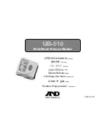
UB-510
Brand: A&D Pages: 50
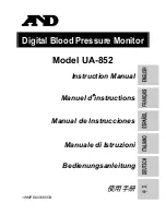
UA-852
Brand: A&D Pages: 20
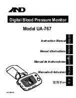
UA-767
Brand: A&D Pages: 14
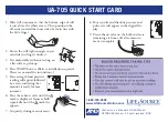
UA-705
Brand: A&D Pages: 3
UA-621
Brand: A&D Pages: 42
UA-1030T
Brand: A&D Pages: 2
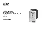
ESSENTIAL UB-525
Brand: A&D Pages: 48

P60W38 Series
Brand: Zenith Pages: 36

P42W34P
Brand: Zenith Pages: 36

L30W26
Brand: Zenith Pages: 56

SyncMaster 320TSn-2
Brand: Samsung Pages: 21

SyncMaster LD190G
Brand: Samsung Pages: 67

SyncMaster 460UT
Brand: Samsung Pages: 25

E-MOTIVE ATOM ATOM01-000-0-40-900
Brand: AVIRE Pages: 14

CF015Q
Brand: CFORCE Pages: 15

iF251
Brand: I-Inc Pages: 20


