


P.P.H. WObit E.K.J. Ober s.c.
62-045 Pniewy, Dęborzyce 16
tel. 61 22 27 422, fax. 61 22 27 439
e-mail: [email protected]
www.wobit.com.pl
User manual
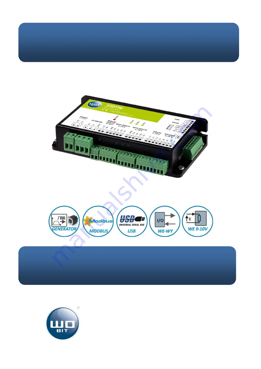
SID116
DC motor driver
with USB and RS485 – Modbus interfaces
The WOBIT SID116 offers advanced features for users seeking top-quality performance. Find the comprehensive User Manual available for free download at manualshive.com. This manual will guide you through the product's functions and settings, ensuring a seamless user experience. Get your manual today and unleash the full potential of your device.
P.P.H. WObit E.K.J. Ober s.c.
62-045 Pniewy, Dęborzyce 16
tel. 61 22 27 422, fax. 61 22 27 439
e-mail: [email protected]
www.wobit.com.pl
User manual
SID116
DC motor driver
with USB and RS485 – Modbus interfaces


