Wind & Solar FT-300, User Manual
The Wind & Solar FT-300 User Manual is a comprehensive guide designed to help users efficiently harness renewable energy. Available for free download from our website, this manual offers step-by-step instructions and valuable insights to maximize the potential of the FT-300, empowering users to contribute to a sustainable future.
Share
Download


Reviews:
No comments
Related manuals for FT-300
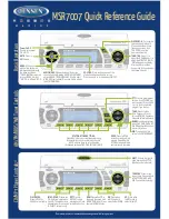
MSR7007
Brand: Jensen Pages: 2

Contour 200i Air
Brand: Pure Digital Pages: 28

WS-01
Brand: Ipevo Pages: 34

43231
Brand: Lindy Pages: 8

WS-7394U
Brand: La Crosse Technology Pages: 24

SOLARIS
Brand: Terraillon Pages: 20

LOWSB510PB
Brand: Logia Pages: 38

LOWSC510WB
Brand: Logia Pages: 40

LOWSC715FWB10
Brand: Logia Pages: 21

LOWSC713SWB
Brand: Logia Pages: 20

Viper CE Cradle
Brand: Datalogic Pages: 18

GPS188IPXI
Brand: Goodmans Pages: 17

810-1461
Brand: La Crosse Pages: 6

11501
Brand: Monoprice Pages: 33

308-1415
Brand: La Crosse Technology Pages: 8

S20iBT12E
Brand: Sandstorm Pages: 96

00076045 "EWS-800"
Brand: Hama Pages: 136

ISD-190
Brand: Marine dock Pages: 10


