


Kunststoffschweißtechnik
WIDOS
Einsteinstr. 5
Phone ++49 7152 9939 - 0
W. Dommer Söhne GmbH
D-71254 Ditzingen-Heimerdingen
Fax
++49 7152 9939 - 40
website: www.widos.de
email: [email protected]
Headquarters: D-71254 Ditzingen-Heimerdingen Country court Stuttgart HRB 200973 Managing director: Jürgen Dommer
Working Instructions
Translation
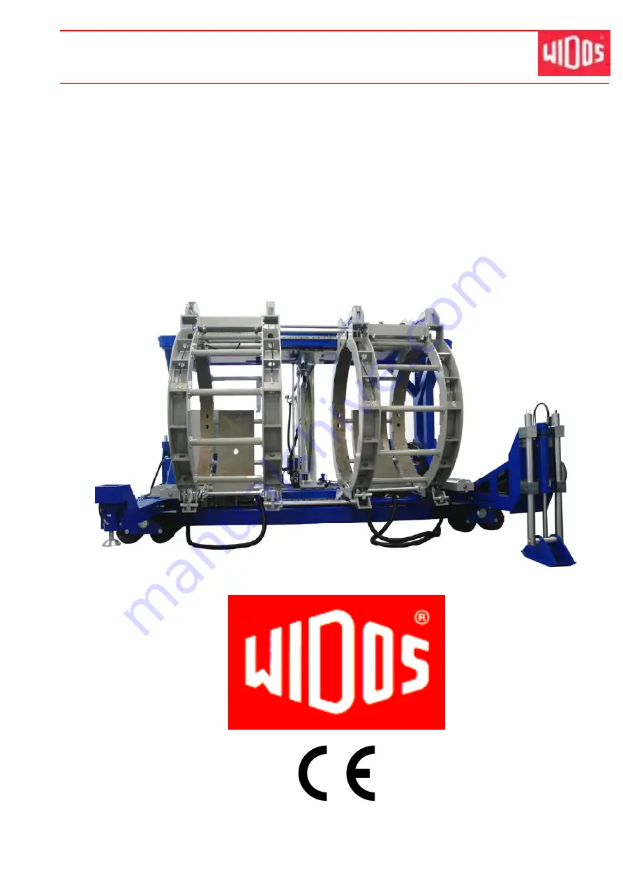
Heating element butt welding machine
WIDOS 25000 mobile
Keep for further use!


