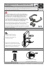
background image

DE

 | 

EN

 | 

FR

SD4ICS0xSE89

SD4ICS1xSE89

SD4ICA01

Sicherheitszuhaltung elektromagnetisch / 

Sicherheitsschalter mit Zuhaltefunktion

Safety Interlock electromagnetic /  
Safety Switch with interlocking function
Dispositif de verrouillage de sécurité electromagnétique / 

Interrupteur de sécurité avec fonction de verrouillage

Betriebsanleitung

Operating Instructions
Notice d’instructions

Original der Betriebsanleitung


Translation of the Original Operating Instruction  

 Traduction du manuel d’instruction original

Technische Änderungen vorbehalten


Subject to change without notice 

Sous réserve de modifications techniques

SAP NR. 89120

Version: 2.4.0

Stand / Staus / Date:  14.06.2021

www.wenglor.com

Summary of Contents for SD4ICA01

Page 1: ...lectromagn tique Interrupteur de s curit avec fonction de verrouillage Betriebsanleitung Operating Instructions Notice d instructions Original der Betriebsanleitung Translation of the Original Operati...

Page 2: ...eise 12 6 Inbetriebnahme 14 6 1 Elektrischer Anschluss 14 6 1 1 Arbeitsweise der Sicherheitsausg nge 14 6 1 2 Anforderungen an eine nachgeschaltete Auswertung 15 6 1 3 Reihenschaltung 15 6 1 4 Anschlu...

Page 3: ...orisiertes Fachpersonal durchgef hrt werden Installieren und nehmen Sie das Ger t nur dann in Betrieb wenn Sie die Betriebsanleitung gelesen und verstanden haben und Sie mit den geltenden Vorschriften...

Page 4: ...ngs ber wachung SD4ICS0xSE89 gekennzeichnet mit dem Symbol einzusetzen Bei der Bet tiger berwachten Variante SD4ICS1xSE89 handelt es sich um einen Sicherheitsschalter mit einer Zuhaltefunktion f r den...

Page 5: ...eden wird den Tod oder eine schwere Verletzung zur Folge haben kann VORSICHT Das Signalwort bezeichnet eine Gef hrdung mit einem niedrigen Risikograd die wenn sie nicht vermieden wird eine geringf gig...

Page 6: ...einer Anlage oder Maschine die korrekte Gesamtfunktion sicherzustellen F r Sch den und Betriebsst rungen die durch Montagefehler oder Nichtbeachtung dieser Betriebsanleitung entstehen wird keine Haftu...

Page 7: ...nsspannung Ui 32 V Bemessungsbetriebsspannung Ue 24 V Bemessungsbetriebsstrom Ie 1 1 A Bedingter Bemessungskurzschlussstrom 100 A Externe Leitungs und Ger teabsicherung 2 A gG Einschaltdauer Magnet 10...

Page 8: ...ten Geh usematerial Kunststoff glasfaserverst rkt Thermoplast selbstverl schend Anschlussart M12 1 8 polig Anzugsdrehmoment 8 Nm Schwingfestigkeit 10 150 Hz 0 35 mm 5 g Schockfestigkeit 30 g 11 ms Zuh...

Page 9: ...Abh ngigkeit zum Ausgangs strom Permanentmagnet SD4ICS01SA89 SD4ICS03SA89 SD4ICS13SA89 SD4ICS02SA89 SD4ICS04SA89 SD4ICS14SA89 nein typisch 15 N Elektrische Rastung SD4ICS01SA89 SD4ICS02SA89 SD4ICS03S...

Page 10: ...Sicherheitsausgang Mag Magnetansteuerung 4 2 Geh useabmessungen SD4ICSxxSE89 SD4ICA01 40 6 2 68 92 165 5 11 8 13 5 40 1 M12 10 6 15 6 M 4 3 Erg nzende Produkte siehe Katalog wenglor bietet Ihnen die...

Page 11: ...tisch Sicherheitsschalter mit Zuhaltefunktion 4 4 Aufbau SD4ICSxxSE89 1 1 2 2 4 5 3 4 1 1 Befestigungsl cher Permanentmagnet Diagnose LEDs gr n rot gelb Typenschild und aktive Fl che f r Verstelltarge...

Page 12: ...ffnungen durch die mitgelieferten Stopfen verschlie en Bei Bedarf k nnen diese durch Druck am oberen Ende bei Montage mit Stecker nach unten bzw durch rechtsseitigen Druck auf die Stopfen der Ankerpla...

Page 13: ...r Versatz und Wirkrichtung der Zuhaltekraft Montage mit ZMBSD0001 2 1 3 4 5 6 7 8 9 44 16 24 63 45 92 120 6 5 Abb 2 Montage SD4ICSxxSE89 mit Montagewinkel ZMBSD0001 1 Innensechskantschraube M6 2 Schei...

Page 14: ...ie Zuhaltung ist gesperrt Magnetkraft ist 500 N Das Entsperren der Sicherheitszuhaltung f hrt zur Abschaltung der Sicherheitsausg nge innerhalb der Risikozeit Die entsperrte Sicher heitszuhaltung kann...

Page 15: ...tung vorzunehmen Beim Anschluss des Sicherheits Sensors an elektronische Sicherheitsauswertungen empfehlen wir eine Diskrepanz zeit von mindestens 100 ms einzustellen Die Sicherheitseing nge der Auswe...

Page 16: ...sucht nach dem Verstelltarget Die Sicherheitsausg nge bleiben bei aktiviertem Verstellmodus abgeschaltet 4 Verstelltarget wieder vom Ger t entfernen Der SD4I zeigt durch mehrmaliges kurzes Blinken de...

Page 17: ...n 6 3 Gewaltsames Trennen von Sicherheitszuhaltung und Bet tiger Nur in Verbindung mit der Variante Zuhaltung berwacht SD4ICS0xSE89 Die Sicherheitszuhaltung hat eine Zuhaltekraft F von 500 N Durch unz...

Page 18: ...Versatz von Bet tigereinheit und Sicherheitszuhaltung pr fen Max Winkelversatz siehe Abschnitt Montage pr fen Unversehrtheit der Leitungseinf hrung und anschl sse Schaltergeh use auf Besch digungen b...

Page 19: ...am Ausgang OSSD 1 obwohl der Ausgang abgeschaltet ist 2 Blinkpulse Fehler warnung an Ausgang OSSD 2 30 min Fehler im Ausgangstest oder Spannung am Ausgang OSSD 2 obwohl der Ausgang abgeschaltet ist 3...

Page 20: ...al Magnetansteuerung IN Normaler Ablauf T r wurde gesperrt OUT T r konnte nicht gesperrt werden oder Fehler OUT Abb 3 Verhalten Signalausgang Legende Sperren Entsperren T r ge ffnet Sperrzeit typisch...

Page 21: ...blinkt 2 blinkt 2 0 V 0 V Tab 3 Diagnoseinformation f r zuhaltungs berwachte Variante SD4ICS0xSE89 Systemzustand Magnet ansteuerung LED Sicherheits ausg nge Signal ausgang Mag gr n rot gelb OSSD 1 OSS...

Page 22: ...r Ursache wieder zur ckgenommen Wenn mehr als ein Fehler auf den Sicherheitsausg ngen erkannt wird verriegelt sich das Ger t elektro nisch und eine normale Fehlerquittierung ist nicht mehr m glich Zum...

Page 23: ...rheitszuhaltung elektromagnetisch Sicherheitsschalter mit Zuhaltefunktion 10 3 EU Konformit tserkl rung Kopie der Original Konformit tserkl rung Das Original kann unter www wenglor com herunter gelade...

Page 24: ...structions 34 6 Initial Start Up 36 6 1 Electrical Connection 36 6 1 1 Mode of Operation of the Safety Outputs 36 6 1 2 Requirements for Downstream Evaluation 37 6 1 3 Series Connection 37 6 1 4 Conne...

Page 25: ...authorised by the plant operator only Please make sure that you have read and understood these operating instructions and that you know all applicable legislations regarding occupational safety and ac...

Page 26: ...SE89 with the monitored interlock is to be used labelled with the symbol The actuator monitoring variant B SD4IC S1xSE89 is a safety switch with an interlock function for process protection NOTE In ac...

Page 27: ...re listed below WARNING This word indicates a hazard with a medium degree of risk which if not avoided may result in death or severe injury CAUTION This word indicates a hazard with a low degree of ri...

Page 28: ...verall functioning We shall accept no liability for damages and malfunctions resulting from defective mounting or failure to comply with this operating instructions manual The manufacturer shall accep...

Page 29: ...e Ue 24 V Rated operating current Ie 1 1 A Conditional rated short circuit current 100 A External line and equipment protection 2 A gG Duty cycle of magnet 100 Response time 150 ms Risk time 150 ms Re...

Page 30: ...0 to 150 Hz 0 35 mm 5 g Shock resistance 30 g 11 ms Locking force Fmax typical 750 N Locking force F guaranteed 500 N Assured switching distance sao 0 mm Assured switch off distance sar 1 mm Service l...

Page 31: ...D4ICS02SA89 SD4ICS03SA89 SD4ICS04SA89 SD4IC S13SA89 SD4ICS14SA89 No 30 to 100 N Other Data Suitable actuator SD4ICA01 Actuator Electrical Data Temperature range 25 to 55 C Mechanical Data Housing mate...

Page 32: ...SD4ICA01 40 6 2 68 92 165 5 11 8 13 5 40 1 M12 10 6 15 6 M 4 3 Complementary Products see catalog wenglor offers Connection Technology for field wiring Suitable Connection Technology No 89 Mounting S...

Page 33: ...y Switch with interlocking function 4 4 Layout SD4ICSxxSE89 1 1 2 2 4 5 3 4 1 1 Mounting holes Permanent Magnet Diagnostic LEDs green red yellow Rating plate and active surface for adjustment target b...

Page 34: ...with the included plugs If it should become necessary these can be removed by applying pressure to the top end with plug pointing down during installation or by applying pressure to the right hand si...

Page 35: ...lateral offset and Effective Direction of the Locking Force Installation with ZMBSD0001 2 1 3 4 5 6 7 8 9 44 16 24 63 45 92 120 6 5 Figure 2 Mounting SD4ICSxxSE89 with mounting bracket ZMBSD0001 1 M6...

Page 36: ...fety outputs are switched on when the actuator is in contact with the Guard Locking Device and the magnet is activated The safety outputs are switched off within the specified risk time when the Guard...

Page 37: ...ents a risk analysis must be conducted If the safety sensor is connected to electronic safety monitoring modules we recommend that you set a discrepancy time of min 100 ms The safety inputs of the saf...

Page 38: ...s for the Adjusting Target The safety outputs remain deactivated when the adjusting mode is active 4 Remove the Adjusting Target from the device again The yellow LED at the SD4I indicates the currentl...

Page 39: ...residual magnetism 6 3 Forcible Separation of the Guard Locking Device and the Actuator Only in connection with Guard locking device monitored SD4ICS0xSE89 The Guard Locking Device has a maximum latch...

Page 40: ...ocking Device and actuator for secure seating Check maximum lateral offset of the actuator unit and the Guard Locking Device Check maximum angular offset see Installation Instructions The cable gland...

Page 41: ...al though the output is switched off 2 blinks Error warning at output OSSD 2 30 min Output test error or voltage at output OSSD 2 al though the output is switched off 3 blinks Error warning Cross circ...

Page 42: ...put signal magnet activation IN Normal sequence door has been locked OUT Door could not be locked or error OUT Figure 3 Signal Output Performance Key Lock Unlock Door open Lock out time typical 100 15...

Page 43: ...Table 3 Diagnostic function of SD4ICS0xSE89 variant guard locking device monitored System Status Magnet Activation LED Safety Outputs OSSD 1 OSSD 2 Mag Green Red Yellow OSSD 1 OSSD 2 Signal Door open...

Page 44: ...er the cause has been eliminated If more than one error is detected at the safety outputs the device is electronically disabled and normal error acknowledgment is no longer possible In this case the d...

Page 45: ...fety Interlocks electromagnetic Safety Switch with interlocking function 10 3 EU Declaration of Conformity Copy of the original declaration of conformity The original can be downloaded from www wenglo...

Page 46: ...en service 58 6 1 Raccordement lectrique 58 6 1 1 Mode fonctionnement des sorties de s curit 58 6 1 2 Sp cifications d une unit d valuation en aval 59 6 1 3 Montage en s rie 59 6 1 4 Exemple de racco...

Page 47: ...n est autoris effectuer les instructions de ce mode d emploi Il est important de lire et de comprendre le mode d emploi avant l installation et la mise en service du composant Vous devez galement conn...

Page 48: ...rotecteur ferm il s agit d un interrupteur de s curit avec fonction de verrouillage pour la protection du processus REMARQUE Les interverrouillages de s curit sont class s selon EN ISO 14119 dans la c...

Page 49: ...ra ner la mort ou des blessures graves PRUDENCE Le mot de signalisation d signe un risque avec un faible niveau de danger qui s il n est pas cart peut entra ner des blessures l g res ou mod r es ATTEN...

Page 50: ...ant d une installation globale ou d une machine Il est de la responsabilit du fabricant d une installation ou d une machine d assurer le fonctionnement global correct Nous d clinons toute responsabili...

Page 51: ...Uimp 0 8 kV Cat gorie de surtension III Degr de pollution 3 Tension d isolement assign e Ui 32 V Tension de service assign e Ue 24 V Courant de service assign Ie 1 1 A Courant de court circuit assign...

Page 52: ...e assign e Ue2 24 V Excitation de l aimant Mag Plage de tension 3 5 V niveau bas bloc secteur TBTP stabilis selon CEI 60204 1 15 30 V niveau haut bloc secteur TBTP stabilis selon CEI 60204 1 typiqueme...

Page 53: ...e de fonctionnement Induction Niveau de codage EN ISO 14119 faible Verrouillage lectromagn tique Montage en s rie Nombre d appareils illimit tenir compte de la protection de ligne externe Longueur de...

Page 54: ...SD Sortie de s curit Mag Excitation de l aimant 4 2 Dimensions du bo tier SD4ICSxxSE89 SD4ICA01 40 6 2 68 92 165 5 11 8 13 5 40 1 M12 10 6 15 6 M 4 3 Produits compl mentaires voir catalogue wenglor vo...

Page 55: ...s curit avec fonction de verrouillage 4 4 Structure SD4ICSxxSE89 1 1 2 2 4 5 3 4 1 1 Trous de fixation Aimant permanent LED de diagnostic verte rouge jaune Plaque signal tique et surface active pour...

Page 56: ...referm es avec les obturateurs livr s Si n cessaire ceux ci peuvent tre retir s en appuyant sur l extr mit sup rieure en cas de montage avec le connecteur en bas ou en appuyant du c t droit sur les ob...

Page 57: ...calage lat ral maximal autoris et sens d action de la force de verrouillage Montage avec ZMBSD0001 2 1 3 4 5 6 7 8 9 44 16 24 63 45 92 120 6 5 Fig 2 Montage SD4ICSxxSE89 avec querre de montage ZMBSD00...

Page 58: ...rouillage du dispositif de verrouillage de s curit conduit la d sactivation des sorties de s curit avant coulement de la dur e de risque Le dispositif de verrouillage de s curit d verrouill peut tre r...

Page 59: ...s curit il faut effectuer une nouvelle valuation des risques Lorsque le capteur de s curit est raccord des modules de s curit lectroniques nous recomman dons de d finir un temps de discordance d au mo...

Page 60: ...cherche la cible de r glage Les sorties de s curit restent d sactiv es quand le mode de r glage est activ 4 Retirer la cible de r glage nouveau de l appareil Le SD4I indique par plusieurs brefs cligno...

Page 61: ...spositif de verrouillage de s curit et de l actionneur Le dispositif de verrouillage de s curit a une force de verrouillage F de 500 N Uniquement en liaison avec la version surveillance de l interverr...

Page 62: ...V rifier le d calage lat ral maximal de l actionneur et du dispositif de verrouillage de s curit V rifier le d calage angulaire maximal voir la section Montage Contr ler que les passe c bles et racco...

Page 63: ...a sortie soit d sactiv e 2 clignote ments Erreur avertisse ment sur la sortie OSSD 2 30 min Erreur dans le test de sortie ou tension sur la sortie OSSD 2 bien que la sortie soit d sactiv e 3 clignote...

Page 64: ...mant IN D roulement normal la porte a t verrouill e OUT La porte n a pas pu tre verrouill e ou erreur OUT Fig 3 Comportement de la sortie de signal L gende Verrouiller D verrouiller Porte ouverte Temp...

Page 65: ...e de la version SD4ICS0xSE89 avec surveillance de l interverrouillage tat du syst me Excitation aimant LED Sorties de s curit Sortie de signal Mag vert rouge jaune OSSD 1 OSSD 2 Signal Porte ouverte 0...

Page 66: ...d erreur dispara t apr s suppression de sa cause Si plusieurs erreurs sont d tect es sur les sorties de s curit l appareil se verrouille lectroniquement et un acquittement d erreur normal n est plus...

Page 67: ...illage de s curit Electromagn tiques Interrupteur de s curit avec fonction de verrouillage 10 3 D claration UE de conformit Copie de la d claration de conformit originale L original peut tre t l charg...

Page 68: ...Discover more innovation For additional information about our products please visit www wenglor com...

Reviews: