Weldex WDC-4605XV, Operation Manual
The Weldex WDC-4605XV operation manual is available for free download on our website. This comprehensive manual provides step-by-step instructions on how to effectively operate and maximize the potential of your Weldex WDC-4605XV. Visit manualshive.com now to download your manual and unlock the full potential of your product.
Share
Download


Reviews:
No comments
Related manuals for WDC-4605XV

Apollo Marine 65 Series
Brand: Halma Pages: 2

Pro HD
Brand: XVision Pages: 33

LTV-WL1
Brand: La Crosse Pages: 3

HomeMonitor HD
Brand: Y-cam Pages: 12

Fixed Box Series
Brand: Brickcom Pages: 23

DDF3000AV4-D
Brand: dallmeier Pages: 40

TVIP52500
Brand: Abus Pages: 311

Bullet 2E
Brand: IMOU Pages: 50

KC-2A
Brand: Ultrak Pages: 16

EAR 35
Brand: fadini Pages: 2

Kasa Spot
Brand: TP-Link Pages: 40

AS4CT
Brand: M-system Pages: 4

LIC120SHP
Brand: Longse Pages: 2

DDA kit
Brand: Silent Alert Pages: 2

NDIHX-PTZ2
Brand: NewTek Pages: 44
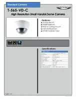
T-565-VD-C
Brand: OPTICOM Pages: 1

CCTV-210
Brand: Steren Pages: 142

IP-CAM555W
Brand: Zip Pages: 27


