


WEINZIERL ENGINEERING GmbH
EN
2013-08-14
Page 1/4
KNX RF/TP Coupler 670
Bidirectional gateway between KNX-RF and the KNX-bus
Installation and operating manual
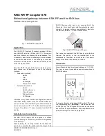
Fig. 1: KNX RF/TP Coupler 670
Application
The KNX RF/TP Coupler 670 connects wireless KNX de-
vices (KNX-RF) with the KNX bus (KNX TP). The commu-
nication is bidirectional, allowing the state-feedback. This,
for example, also allows the switching of wired actuators
via a wireless radio switch or the switching of a wireless
actuator via a wired switch. In addition the WaveLink can
act as a radio transmitter.
The KNX RF/TP Coupler 670 comes with 24 channels.
Each channel can be assigned to one of the following
functions:
*
As receiver (actuator)
-
Switch
-
Dim
-
Blinds
-
LED-display
-
Temperature sensor
*
As transmitter (sensor)
-
Switch
-
Switch with scene
-
Dim with scene
-
Blinds with scene
-
LED-display
In addition, every channel which is configured as receiver
forward the battery status of the connected wireless de-
vices on the bus. Here, the “battery low” status of the radio
device can only be set “0” to “1” by the radio device itself.
A reset of the status to “0” has to be made from the KNX
bus side.
Installation and connection
The KNX RF/TP Coupler 670 is supplied in a surface
mounted housing. For activation, just connect the gateway
to the KNX bus.
When selecting the mounting location for the WaveLink
you have to consider the position and the range of the
KNX-RF devices which have to be associated with the
WaveLink. You should avoid shielding objects (eg metal
cabinets) or jamming objects (eg computers, electronic
transformers, ballasts …) close to the WaveLink.
Fig. 2: KNX RF/TP Coupler 670 open
The device is connected to the KNX bus by using the bus
terminal. The polarity of the bus terminal has to be
considered (s. inscription on circuit board). The power
supply of the device is exclusively on the bus.
Initial state
A new WaveLink has the physical address of 15.15.255.
There are no preset group addresses and connections to
KNX-RF devices.
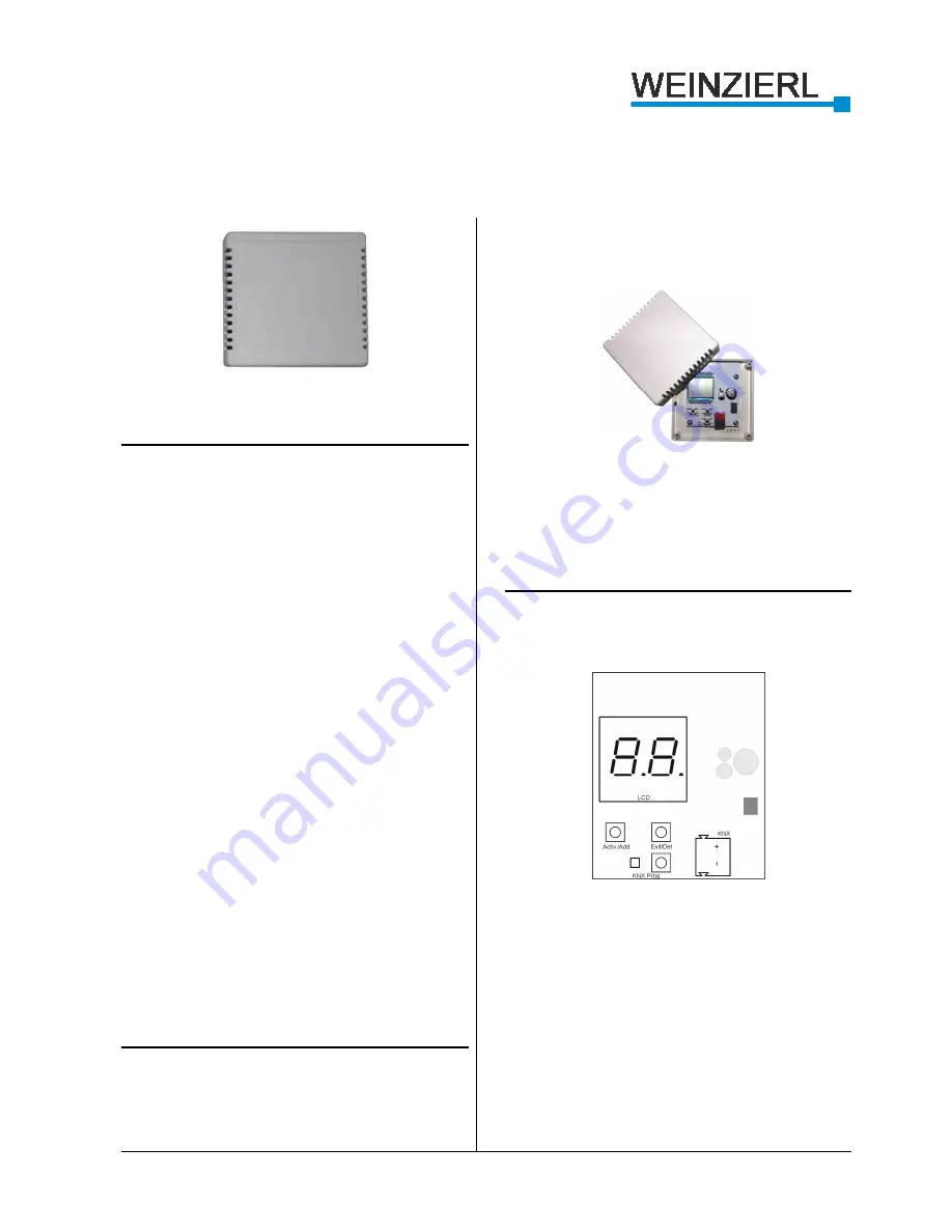
Fig. 3: Device with top open
To program the physical address (KNX) on the ETS, press
the programming key („KNX Prog“). This causes the red
LED to light up. The LED goes out as soon as the device
has received its physical address. The group address and
parameter settings can then be programmed.


